Leave Your Message

How to Choose the Right Electrical Substation?

Choosing the right Electrical Substation is a practical decision with long-term consequences. It affects safety, power quality, operating costs, and future expansion. A suitable design begins with accurate load data, not assumptions. Engineers should examine peak demand, fault levels, voltage requirements, and expected growth over the next decade.

Site conditions matter as much as electrical ratings. Soil resistance, flood exposure, available land, drainage, and transport access can change the entire project plan. A transformer may fit on paper yet create maintenance problems later. Leave working space around every major component. Keep replacement routes realistic. Small details become expensive during an outage.

Experienced project teams compare indoor, outdoor, gas-insulated, and air-insulated solutions against site needs. They review transformer cooling, protection systems, grounding, noise, fire separation, and monitoring capabilities. Designs should reflect applicable IEC, IEEE, and local technical requirements. Independent verification can reveal gaps that internal teams overlook.

The cheapest option is rarely the safest choice. Still, higher cost does not automatically mean better performance. A modern substation can become unnecessarily complex, difficult to maintain, or dependent on scarce parts. That is where careful judgment matters. Ask how operators will work during rain, heat, faults, and planned maintenance. Ask what happens when the original assumptions prove wrong.

There is no universal checklist. A reliable Electrical Substation balances present demand, future resilience, budget limits, environmental conditions, and human experience. The best decision is documented clearly, tested realistically, and reviewed by qualified professionals before construction begins.
How to Choose the Right Electrical Substation?

Define the Substation’s Electrical and Operational Requirements

How to Choose the Right Electrical Substation?

Define the Substation’s Electrical and Operational Requirements

Begin with the load, not the equipment catalog. Record present demand, motor-starting currents, power factor, harmonics, and expected expansion. The IEA Electricity 2024 report forecasts global electricity demand will grow by an average of 3.4% annually through 2026. Your substation should therefore handle realistic future scenarios, not only today’s peak. Define primary and secondary voltages, short-circuit levels, grounding method, protection zones, and acceptable voltage deviation. A neat spreadsheet can still miss a cold-start motor or a sudden solar export condition.

Operational requirements need equal attention. Specify normal, emergency, and maintenance switching arrangements. Decide whether the facility requires N-1 transformer redundancy, automatic transfer, remote control, or local operation during communication failure. The U.S. Department of Energy’s Distribution System Resilience report emphasizes sectionalizing, automation, and faster restoration as practical resilience measures. Select protection settings with coordination studies, arc-flash analysis, and verified fault data. Do not rely on assumptions.

Tips: Build a 24-hour load profile from measured data. Test the worst credible operating case. Leave space for one future feeder, if the site can afford it. During commissioning, compare relay records with the design model. Small mismatches matter. Requirements often change after installation, which is why periodic review should be part of the operating plan.
Assess Site Conditions, Grid Compatibility, and Future Expansion

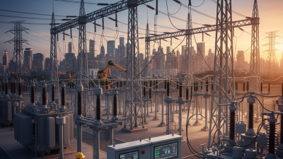
Choosing the right electrical substation starts with a careful study of the site. Check flood levels, soil resistivity, wind exposure, seismic risk, and ambient temperature. A low-lying plot may require raised equipment and improved drainage. Poor soil can increase grounding costs and prolong installation work. Access also matters. Heavy transformers need strong roads, turning space, and safe lifting areas.

Grid compatibility requires more than matching voltage. Confirm frequency, fault levels, phase arrangement, protection settings, and grounding methods with the network operator. Engineers should review load flow, short-circuit performance, harmonics, and voltage stability. Cable routes must suit both the substation layout and existing transmission paths. Small errors here can cause nuisance trips or expensive redesigns. Testing under realistic operating conditions is essential.

Future expansion should influence today’s footprint. Reserve space for additional transformers, switchgear bays, cable ducts, and control equipment. Design foundations and bus sections with practical extensions in mind. Load forecasts are never perfect. They may change with new housing, factories, or renewable generation. Overbuilding wastes capital, yet leaving no expansion space creates a costly constraint. A phased plan, supported by clear maintenance access and reliable monitoring, usually offers better resilience. Sometimes the most convincing design drawing still misses one drainage channel or maintenance route. A site walk can expose that weakness early.

How to Choose the Right Electrical Substation? – Assess Site Conditions, Grid Compatibility, and Future Expansion
Assessment Area Technical Dimension Recommended Screening Criteria Site A Site B Site C Evaluation
Site Conditions
Available land Usable area for switchyard, transformers, control building, roads, drainage, and safety clearances Allow at least 20–30% space beyond the initial layout for future bays and equipment 1.8 ha 3.6 ha 2.4 ha B preferred
Ground bearing capacity Allowable soil bearing pressure for transformer foundations and structures Typically ≥150 kPa, subject to geotechnical design 110 kPa 220 kPa 165 kPa A requires improvement
Flood exposure Finished equipment elevation above the design flood level Equipment platform should be above the applicable design flood level with local safety margin 0.4 m above 1.2 m above 0.7 m above B preferred
Seismic condition Site seismic hazard and equipment anchoring requirements Confirm design spectrum and anchorage requirements through a site-specific study Moderate Low Moderate B preferred
Ambient temperature Expected annual temperature range affecting transformer cooling and equipment ratings Confirm equipment rating for local minimum and maximum temperatures -10 to 38 °C -18 to 42 °C -5 to 35 °C Verify B cooling margin
Environmental conditions Pollution, salt contamination, dust, and humidity affecting insulation coordination Specify appropriate creepage distance and enclosure protection based on local severity Medium High dust Coastal salt exposure Site-specific insulation design
Access and logistics Transport route for power transformers and heavy equipment Roads and gates should support approximately 100–150 t transformer transport, subject to project size Restricted bridge Heavy-haul access Sharp access turn B preferred
Noise and community impact Distance to sensitive receptors and potential transformer noise Maintain separation and apply acoustic controls to meet applicable limits 180 m 420 m 95 m B preferred
Grid Compatibility
Transmission voltage Voltage level available at the connection point Must match the approved grid connection study and required transformation ratio 110 kV 220 kV 110 kV Confirm network connection
Initial transformer capacity Installed transformer rating for the first operating stage Size for forecast demand plus an appropriate planning margin 2 × 40 MVA 2 × 63 MVA 1 × 63 MVA B offers redundancy
Expected peak demand Forecast maximum coincident load at initial operation Transformer capacity should support peak demand without sustained overload 55 MVA 78 MVA 48 MVA A has limited margin
Firm capacity after outage Capacity available after loss of the largest transformer Target depends on reliability requirements; critical loads commonly require N-1 capability 40 MVA 63 MVA 0 MVA B meets N-1 basis
Short-circuit level Prospective three-phase fault current at the connection bus Switchgear interrupting rating must exceed calculated fault current with design margin 25 kA 31.5 kA 18 kA Confirm equipment rating
Protection coordination Compatibility with upstream and downstream relay settings Complete time-current coordination and stability studies before final equipment selection Study required Preliminary pass Study required B advanced
Voltage regulation Expected bus-voltage variation under normal and contingency conditions Maintain the project voltage band established by the grid code and connection agreement ±5.2% ±3.1% ±4.6% B preferred
Reactive power and power factor Reactive power requirement at the point of connection Provide tap control, capacitor banks, reactors, or other equipment as required by the grid study 0.92 lagging 0.96 lagging 0.90 lagging Compensation may be required
Future Expansion
Transformer expansion Space and civil provisions for additional transformer capacity Reserve a complete transformer position, foundation area, fire separation, and oil containment route 1 future position 2 future positions No reserved position B preferred
Future line bays Available positions for additional incoming or outgoing circuits Reserve at least two practical bay positions where load growth is uncertain 1 bay 4 bays 1 bay B preferred
Forecast load growth Expected compound annual growth in peak demand Use an approved demand forecast and test low, base, and high growth scenarios 3.0% per year 5.5% per year 2.0% per year B needs staged planning
Expansion horizon Capacity planning period for future demand and generation changes Typically evaluate a 10–20 year horizon, subject to the utility planning cycle 10 years 20 years 10 years B offers longer horizon
Protection and control scalability Ability to add bays, communication channels, and automation functions Provide spare panels, relay capacity, cable routes, and communication ports Limited spare space 30% spare capacity 15% spare capacity B preferred
Expansion disruption risk Required outages or temporary works during future additions Prefer layouts that allow expansion while maintaining essential service High Low Medium B preferred
Overall Decision
Indicative weighted score Combined result for site conditions, grid compatibility, and expansion readiness Use detailed studies before final investment approval 68 / 100 87 / 100 64 / 100 Site B ranks first
Recommended action Next step before final selection Complete geotechnical, flood, environmental, load-flow, short-circuit, protection, and cost studies Improve ground and access Proceed to detailed design Add transformer and mitigate site constraints B is the strongest candidate
Planning note: The site values are realistic screening-stage project data intended for comparative evaluation. Final substation selection must be validated through site surveys, geotechnical and environmental studies, utility interconnection requirements, load-flow and fault calculations, protection coordination, cost analysis, and applicable electrical safety standards.

Compare Substation Types, Ratings, and Protection Systems

Choosing the right electrical substation starts with comparing its physical design, capacity, and protection requirements. Air-insulated substations suit spacious sites and offer easier visual inspection. Gas-insulated designs need less land and perform well in dense or harsh environments. Hybrid layouts can balance footprint, access, and maintenance needs. The choice depends on available space, climate, contamination, and future expansion.

Ratings must match real operating conditions, not only the present load. Check the highest system voltage, transformer MVA rating, continuous current, and short-circuit withstand level. Temperature, altitude, wind, and humidity can reduce equipment performance. A substation serving a growing industrial area may need spare transformer capacity and additional feeder bays. Small assumptions here become expensive later.

Protection systems require careful coordination. Differential protection can detect internal transformer faults quickly, while overcurrent relays protect feeders and backup circuits. Distance protection may suit longer transmission lines. Breaker-failure protection, surge arresters, grounding, and fire separation add important layers. Relay settings should reflect fault studies and actual operating conditions. Field testing matters; a correct drawing cannot prove a trip circuit works. In practice, teams sometimes focus too heavily on equipment ratings and overlook maintenance access, communication delays, or confusing alarm displays. That deserves a second review.

Evaluate Safety Standards, Reliability, Costs, and Maintenance

Choosing an electrical substation starts with safety, not the lowest quotation. Verify compliance with IEC 61936-1, IEC 60076, and NFPA 70E. These references address clearances, insulation, grounding, arc-flash risks, and transformer performance. Request evidence from factory tests, protection coordination studies, and site commissioning records. A neat enclosure is not enough.

Reliability should be measured under realistic conditions. NERC’s 2024 State of Reliability report identifies extreme weather as an increasing threat to grid performance. Therefore, assess flood height, heat, lightning, salt exposure, and spare-part access. Consider redundant protection, condition monitoring, and offline backup power where failure consequences are severe. Uptime Institute’s 2023 Global Data Center Survey found that 60% of respondents reported outage costs above 100,000 dollars. That figure is not a substation benchmark, but it shows why downtime deserves a financial model.

Purchase price can hide lifecycle costs. Compare losses, cooling energy, civil works, testing, insurance, and replacement lead times over twenty years. Maintenance plans should follow NFPA 70B and include thermal scans, oil testing, relay checks, battery inspections, and cleaning schedules. Use alarm trends, not only annual visits. Reliability calculations may look precise while input data remains weak. Review assumptions with operators who have faced real faults. A cheaper design may become expensive after one avoidable outage.

Select the Best Substation Configuration for the Intended Application

Choosing the right electrical substation starts with the application, not the equipment list. A compact urban site may require gas-insulated switchgear because land is scarce and visual impact matters. An industrial plant may prefer air-insulated switchgear for easier inspection and future extensions. CIGRE technical studies consistently identify space, reliability, maintainability, and environmental conditions as primary configuration factors. The cheapest footprint is not always the lowest-life-cycle-cost option.

Load behavior should shape the single-line diagram. For a radial feeder, one transformer outage can interrupt an entire production line. A ring-bus or double-bus arrangement adds switching flexibility, but also increases protection complexity. The NERC 2024 Long-Term Reliability Assessment projects substantial North American peak-demand growth over the coming decade. That trend supports reserved bays, spare transformer capacity, and clear expansion corridors. Oversizing everything is also imperfect; lightly loaded transformers can waste capital and increase operating losses.

For critical facilities, engineers should test N-1 performance, short-circuit duty, voltage regulation, and emergency restoration time. IEC 60076-7 provides transformer loading guidance, while IEEE Std 242 remains a useful reference for industrial protection coordination. On site, dust, salt, flooding, lightning, and limited crane access can change the preferred design. A transformer with an on-load tap changer may stabilize fluctuating voltage, but it adds maintenance points. Reviewers should challenge the first design. Real operating conditions are often less tidy than the original spreadsheet.

How to Choose the Right Electrical Substation?

Select the Best Substation Configuration for the Intended Application

The chart compares the typical number of circuit breakers required for six circuits: two incoming sources and four outgoing feeders. Single-bus and ring-bus arrangements generally use fewer breakers and are suitable where simplicity and lower capital cost are priorities. Sectionalized, main-and-transfer, double-bus, and breaker-and-a-half arrangements provide greater operational flexibility or continuity, but require additional switching equipment and more complex protection schemes. The final selection should also consider voltage level, short-circuit current, load criticality, expansion plans, protection coordination, and maintenance requirements.