


 Claire
 Mr.Fu
Mr.Fu

 Claire
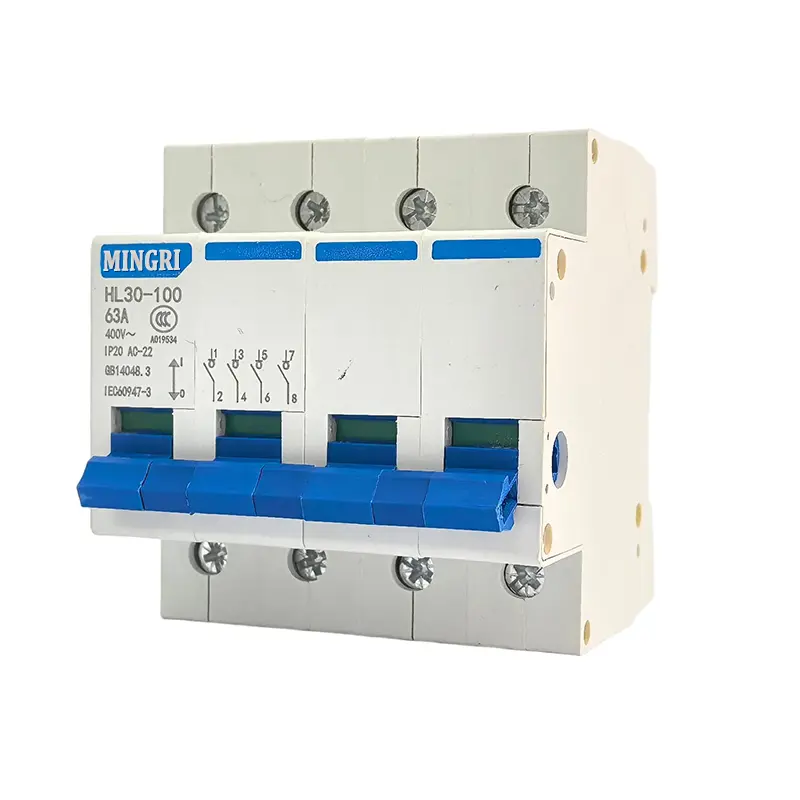


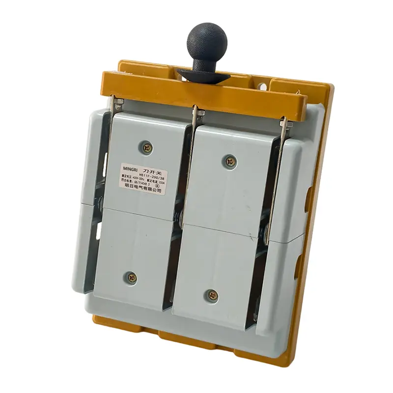
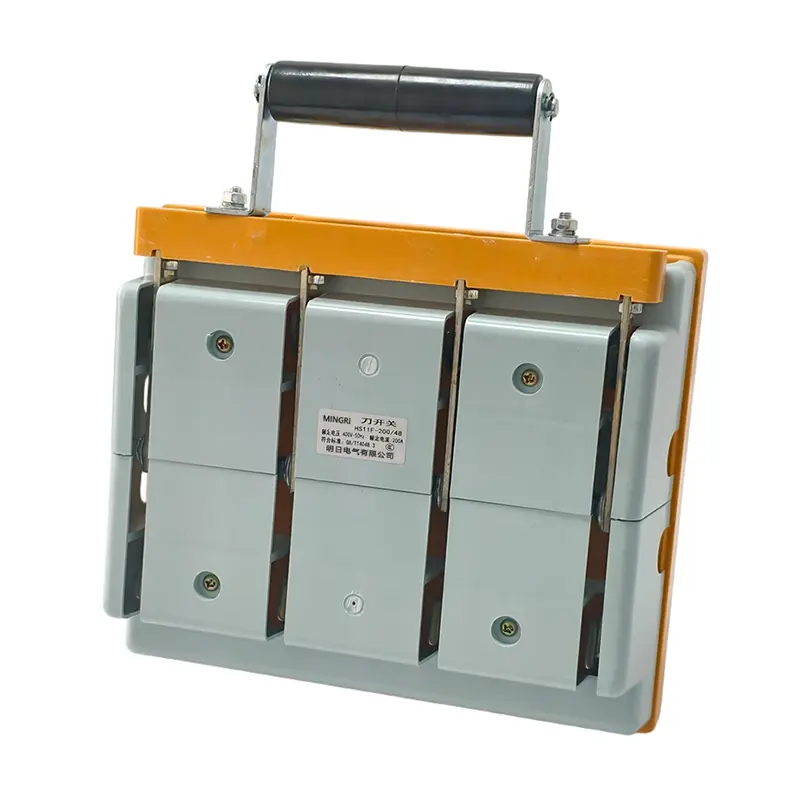
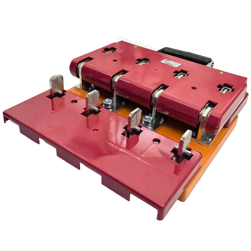

HS11F Double Throw Anti-Error Knife Switch
Type Designation
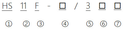
| 1 | Isolator |
| 2 | Handle-operated type |
| 3 | Anti-Error |
| 4 | Rated operating current |
| 5 | Number of poles: 3 poles |
| 6 | 8: Front-mounted wiring (or Front wiring) 9: Rear-mounted wiring (or Rear wiring) |
| 7 | 0: Without auxiliary contact 1: With auxiliar contact |
Structural Features
1. Blade Design & Conductivity
Single-blade (200-400A) and double-blade (600-1500A) structures with tin-plated contacts to reduce resistance and enhance electrical performance.
2. Anti-Error Operation Mechanism
Central rotating shaft design prevents misoperation, ensuring accurate blade positioning and safe handling.
3. Mechanical Interlocking Safety
Interlock devices block accidental closure under load, withstand short-circuit forces, and allow manual unlocking for emergency disconnection.
4. Auxiliary Control Integration
Compatible with L198 auxiliary switches for sequential circuit control (auxiliary contacts operate before main contacts), enabling integration with breaker or motor control systems.
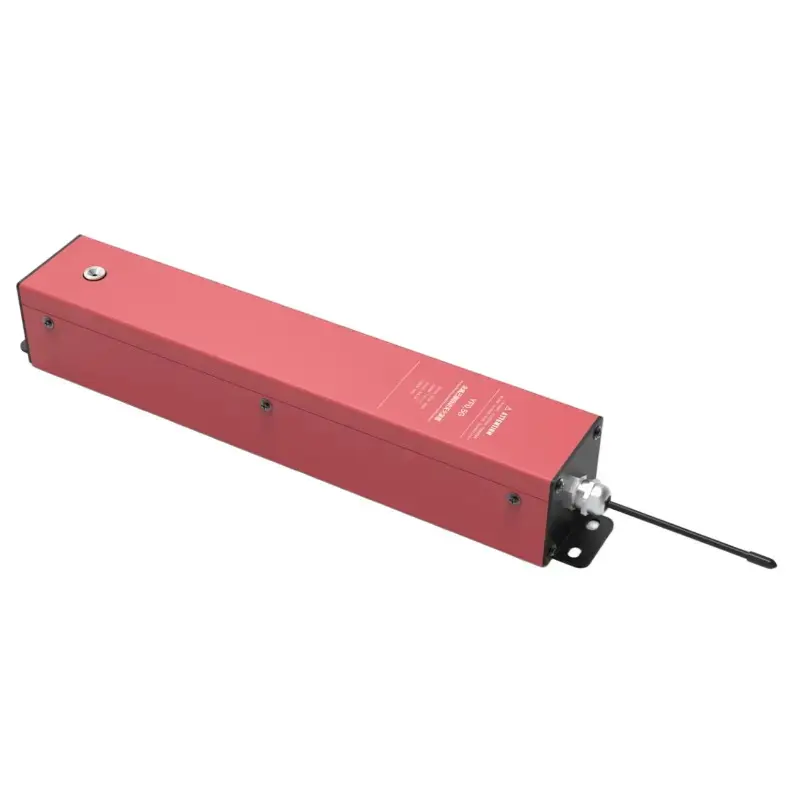
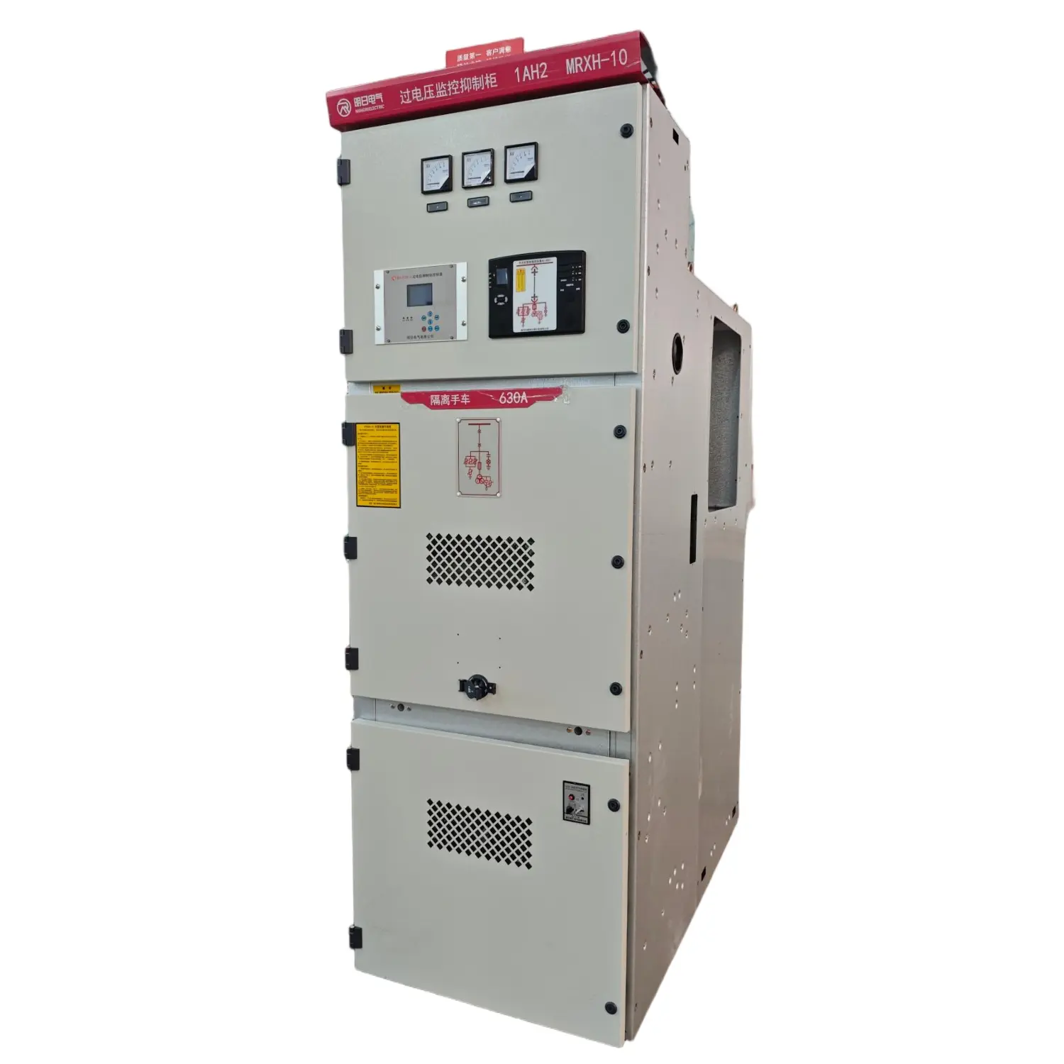
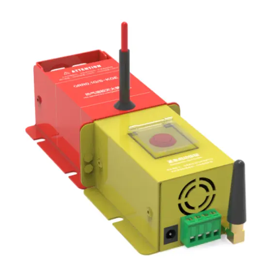
product Display


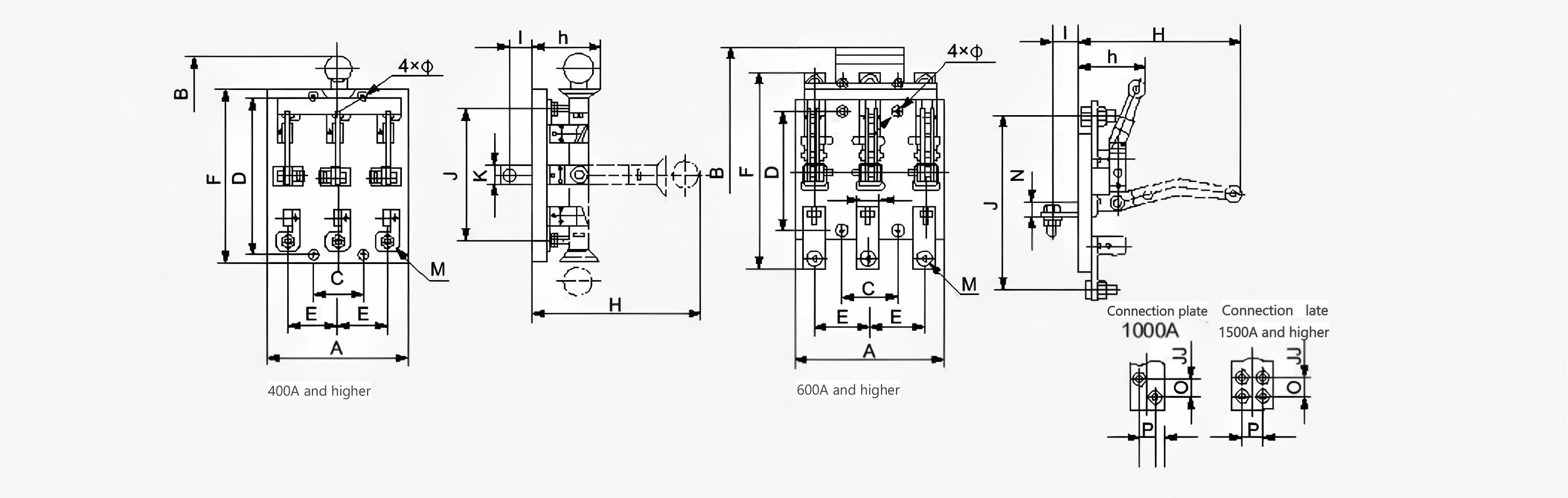
HS11 Protective Knife Switch Outline and Installation Dimensions
The front wiring of HS11F is as shown below.

| Model | specification | 100 | 200 | 400 | ||||||
| 2P | 3P | 4P | 2P | 3P | 4P | 2P | 3P | 4P | ||
| HS11F Protective Front-Connected Knife Transfer Switch | A | 78 | 140 | 170 | 200 | 200 | 270 | 210 | 210 | 300 |
| B | 245 | 290 | 300 | 330 | 330 | 370 | 450 | 450 | 450 | |
| C | - | 40 | 80 | 70 | 70 | 140 | 160 | 80 | 160 | |
| D | 112 | 120 | 120 | 220 | 220 | 220 | 260 | 260 | 260 | |
| E | 40 | 50 | 40 | 140 | 70 | 70 | 80 | 80 | 80 | |
| F | 165 | 165 | 165 | 245 | 245 | 245 | 312 | 312 | 312 | |
| H | 180 | 190 | 200 | 240 | 240 | 240 | 280 | 280 | 300 | |
| h | 70 | 70 | 70 | 100 | 100 | 100 | 110 | 110 | 110 | |
| M | - | - | - | 8 | 8 | 8 | 8 | 8 | 8 | |
| A | 7 | 7 | 7 | 7 | 7 | 7 | 7 | 7 | 7 | |
HS11 Front Terminal Rear Exit Central Handle Knife Transfer Switch Outline and Installation Dimensions
| Model | Specification | 100A,200A | 400A | 600A | 1000A | ||||||||||||
| 1P | 2P | 3P | 4P | 1P | 2P | 3P | 4P | 1P | 2P | 3P | 4P | 1P | 2P | 3P | 4P | ||
| HS11 Front Terminal Rear Exit Central Handle Knife Transfer Switch | A | 100 | 160 | 190 | 265 | 120 | 200 | 220 | 300 | 140 | 240 | 270 | 370 | 160 | 280 | 330 | 450 |
| B | 330 | 330 | 330 | 370 | 395 | 395 | 395 | 455 | 500 | 500 | 460 | 460 | 560 | 560 | 520 | 520 | |
| C | 60 | 120 | 70 | 140 | 80 | 160 | 80 | 160 | 100 | 200 | 100 | 200 | 120 | 240 | 120 | 240 | |
| D | 220 | 220 | 220 | 220 | 260 | 260 | 260 | 260 | 220 | 220 | 220 | 220 | 220 | 220 | 220 | 220 | |
| E | - | 70 | 70 | 70 | - | 80 | 80 | 80 | - | 100 | 100 | 100 | - | 120 | 120 | 120 | |
| F | 245 | 245 | 245 | 245 | 285 | 285 | 285 | 285 | 354 | 354 | 354 | 354 | 374 | 374 | 374 | 374 | |
| H | 240 | 240 | 240 | 240 | 280 | 280 | 280 | 300 | 390 | 390 | 370 | 370 | 450 | 450 | 430 | 430 | |
| h | 100 | 100 | 100 | 100 | 110 | 110 | 110 | 110 | 100 | 100 | 95 | 95 | 150 | 150 | 145 | 145 | |
| I | 35 | 35 | 35 | 35 | 26 | 26 | 26 | 26 | 36 | 36 | 36 | 36 | 36 | 36 | 36 | 36 | |
| J | 170 | 170 | 170 | 170 | 216 | 216 | 216 | 216 | 320 | 320 | 320 | 320 | 304 | 304 | 304 | 304 | |
| K | 20 | 20 | 20 | 20 | 30 | 30 | 30 | 30 | 40 | 40 | 40 | 40 | 50 | 50 | 50 | 50 | |
| N | - | - | - | - | - | - | - | - | 30 | 30 | 30 | 30 | 40 | 40 | 40 | 40 | |
| O | - | - | - | - | - | - | - | - | - | - | - | - | 25 | 25 | 25 | 25 | |
| P | - | - | - | - | - | - | - | - | - | - | - | - | 25 | 25 | 25 | 25 | |
| M | 8 | 8 | 8 | 8 | 12 | 12 | 12 | 12 | 16 | 16 | 16 | 16 | 12 | 12 | 12 | 12 | |
| A | 7 | 7 | 7 | 7 | 7 | 7 | 7 | 7 | 9 | 9 | 9 | 9 | 9 | 9 | 9 | 9 | |
| Model | Specification | 1500A | 2000A | 3000A | |||||||||
| 1P | 2P | 3P | 4P | 1P | 2P | 3P | 4P | 1P | 2P | 3P | 4P | ||
| HS11 Front Terminal Rear Exit Central Handle Knife Transfer Switch | A | 170 | 300 | 380 | 510 | 240 | 400 | 500 | 680 | 260 | 460 | 600 | 800 |
| B | 580 | 580 | 540 | 540 | 680 | 680 | 680 | 680 | 710 | 710 | 710 | 710 | |
| C | 130 | 260 | 130 | 260 | 180 | 360 | 180 | 360 | 200 | 400 | 200 | 400 | |
| D | 260 | 260 | 260 | 260 | 240 | 240 | 240 | 240 | 280 | 280 | 280 | 280 | |
| E | - | 130 | 130 | 130 | t80 | 180 | 180 | 180 | 200 | 200 | 200 | 200 | |
| F | 434 | 434 | 434 | 434 | 480 | 480 | 480 | 480 | 540 | 540 | 540 | 540 | |
| H | 470 | 470 | 450 | 450 | 380 | 380 | 380 | 380 | 390 | 390 | 390 | 390 | |
| h | 160 | 160 | 150 | 150 | 170 | 170 | 170 | 170 | 180 | 180 | 180 | 180 | |
| 1 | 32 | 32 | 32 | 32 | 48 | 48 | 48 | 48 | 50 | 50 | 50 | 50 | |
| J | 340 | 340 | 340 | 340 | 370 | 370 | 370 | 370 | 404 | 404 | 404 | 404 | |
| K | 70 | 70 | 70 | 70 | 100 | 100 | 100 | 100 | 120 | 120 | 120 | 120 | |
| N | 46 | 46 | 46 | 46 | 50 | 50 | 50 | 50 | 50 | 50 | 50 | 50 | |
| O | 35 | 35 | 35 | 35 | 40 | 40 | 40 | 40 | 45 | 45 | 45 | 45 | |
| P | 35 | 35 | 35 | 35 | 55 | 55 | 55 | 55 | 68 | 68 | 68 | 68 | |
| M | 12 | 12 | 12 | 12 | 12 | 12 | 12 | 12 | 16 | 16 | 16 | 16 | |
| A | 9 | 9 | 9 | 9 | 11 | 11 | 11 | 11 | 13 | 13 | 13 | 13 | |
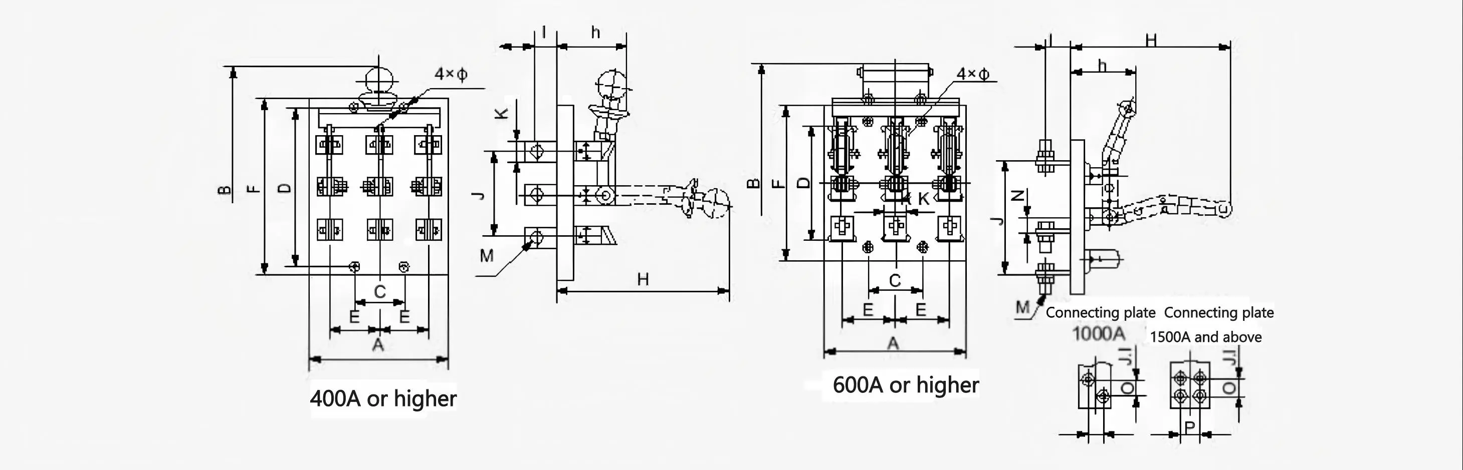
HS11 Rear Terminal Central Handle Knife Transfer Switch Outline and Installation Dimensions
| Model | specification | 100A,200A | 400A | 600A | 1000A | ||||||||||||
| 1P | 2P | 3P | 4P | 1P | 2P | 3P | 4P | 1P | 2P | 3P | 4P | 1P | 2P | 3P | 4P | ||
| HS11 Front Terminal Rear Exit Central Handle Knife Transfer Switch | A | 100 | 170 | 200 | 270 | 120 | 200 | 220 | 300 | 140 | 240 | 270 | 370 | 160 | 280 | 330 | 450 |
| B | 330 | 330 | 330 | 370 | 395 | 395 | 395 | 455 | 500 | 500 | 460 | 460 | 560 | 560 | 520 | 520 | |
| C | 70 | 140 | 70 | 140 | 80 | 160 | 80 | 160 | 100 | 200 | 100 | 200 | 120 | 240 | 120 | 240 | |
| D | 220 | 220 | 220 | 220 | 260 | 260 | 260 | 260 | 300 | 300 | 300 | 300 | 350 | 350 | 350 | 350 | |
| E | - | 70 | 70 | 70 | - | 80 | 80 | 80 | - | 100 | 100 | 100 | - | 120 | 120 | 120 | |
| F | 245 | 245 | 245 | 245 | 285 | 285 | 285 | 285 | 340 | 340 | 340 | 340 | 390 | 390 | 390 | 390 | |
| H | 240 | 240 | 240 | 240 | 280 | 280 | 280 | 300 | 330 | 330 | 310 | 310 | 380 | 380 | 360 | 360 | |
| h | 120 | 120 | 120 | 120 | 135 | 135 | 135 | 145 | 140 | 140 | 125 | 125 | 175 | 175 | 160 | 160 | |
| I | 35 | 35 | 35 | 35 | 26 | 26 | 26 | 26 | 36 | 36 | 36 | 36 | 36 | 36 | 36 | 36 | |
| J | 120 | 120 | 120 | 120 | 140 | 140 | 140 | 140 | 220 | 220 | 220 | 220 | 250 | 250 | 250 | 250 | |
| K | 20 | 20 | 20 | 20 | 30 | 30 | 30 | 30 | 40 | 40 | 40 | 40 | 50 | 50 | 50 | 50 | |
| N | - | - | - | - | - | - | - | - | 30 | 30 | 30 | 30 | 40 | 40 | 40 | 40 | |
| 0 | - | - | - | - | - | - | - | - | - | - | - | - | 25 | 25 | 25 | 25 | |
| P | - | - | - | - | - | - | - | - | - | - | - | - | 25 | 25 | 25 | 25 | |
| M | 8 | 8 | 8 | 8 | 12 | 12 | 12 | 12 | 16 | 16 | 16 | 16 | 12 | 12 | 12 | 12 | |
| A | 7 | 7 | 7 | 7 | 7 | 7 | 7 | 7 | 9 | 9 | 9 | 9 | 9 | 9 | 9 | 9 | |
| Model | specification | 1500A | 2000A | 3000A | |||||||||
| 1P | 2P | 3P | 4P | 1P | 2P | 3P | 4P | 1P | 2P | 3P | 4P | ||
| HS11 Rear Terminal Central Handle Knife Transfer Switch | A | 170 | 300 | 380 | 510 | 240 | 400 | 500 | 680 | 260 | 460 | 600 | 800 |
| B | 580 | 580 | 540 | 540 | 680 | 680 | 680 | 680 | 710 | 710 | 710 | 710 | |
| C | 130 | 260 | 130 | 260 | 180 | 360 | 180 | 360 | 200 | 400 | 200 | 400 | |
| D | 410 | 410 | 410 | 410 | 240 | 240 | 240 | 240 | 280 | 280 | 280 | 280 | |
| E | - | 130 | 130 | 130 | 180 | 180 | 180 | 180 | 200 | 200 | 200 | 200 | |
| F | 450 | 450 | 450 | 450 | 420 | 420 | 420 | 420 | 500 | 500 | 500 | 500 | |
| H | 390 | 390 | 370 | 370 | 380 | 380 | 380 | 380 | 390 | 390 | 390 | 390 | |
| h | 175 | 175 | 160 | 160 | 170 | 170 | 170 | 170 | 180 | 180 | 180 | 180 | |
| I | 32 | 32 | 32 | 32 | 48 | 48 | 48 | 48 | 50 | 50 | 50 | 50 | |
| J | 285 | 285 | 285 | 285 | 310 | 310 | 310 | 310 | 330 | 330 | 330 | 330 | |
| K | 70 | 70 | 70 | 70 | 100 | 100 | 100 | 100 | 120 | 120 | 120 | 120 | |
| N | 46 | 46 | 46 | 46 | 50 | 50 | 50 | 50 | 50 | 50 | 50 | 50 | |
| O | 35 | 35 | 35 | 35 | 40 | 40 | 40 | 40 | 45 | 45 | 45 | 45 | |
| P | 35 | 35 | 35 | 35 | 55 | 55 | 55 | 55 | 68 | 68 | 68 | 68 | |
| M | 12 | 12 | 12 | 12 | 12 | 12 | 12 | 12 | 16 | 16 | 16 | 16 | |
| A | 9 | 9 | 9 | 9 | 11 | 11 | 11 | 11 | 13 | 13 | 13 | 13 | |