


 Claire
 Mr.Fu
Mr.Fu

 Claire
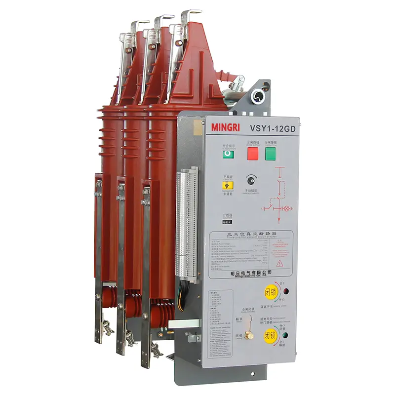
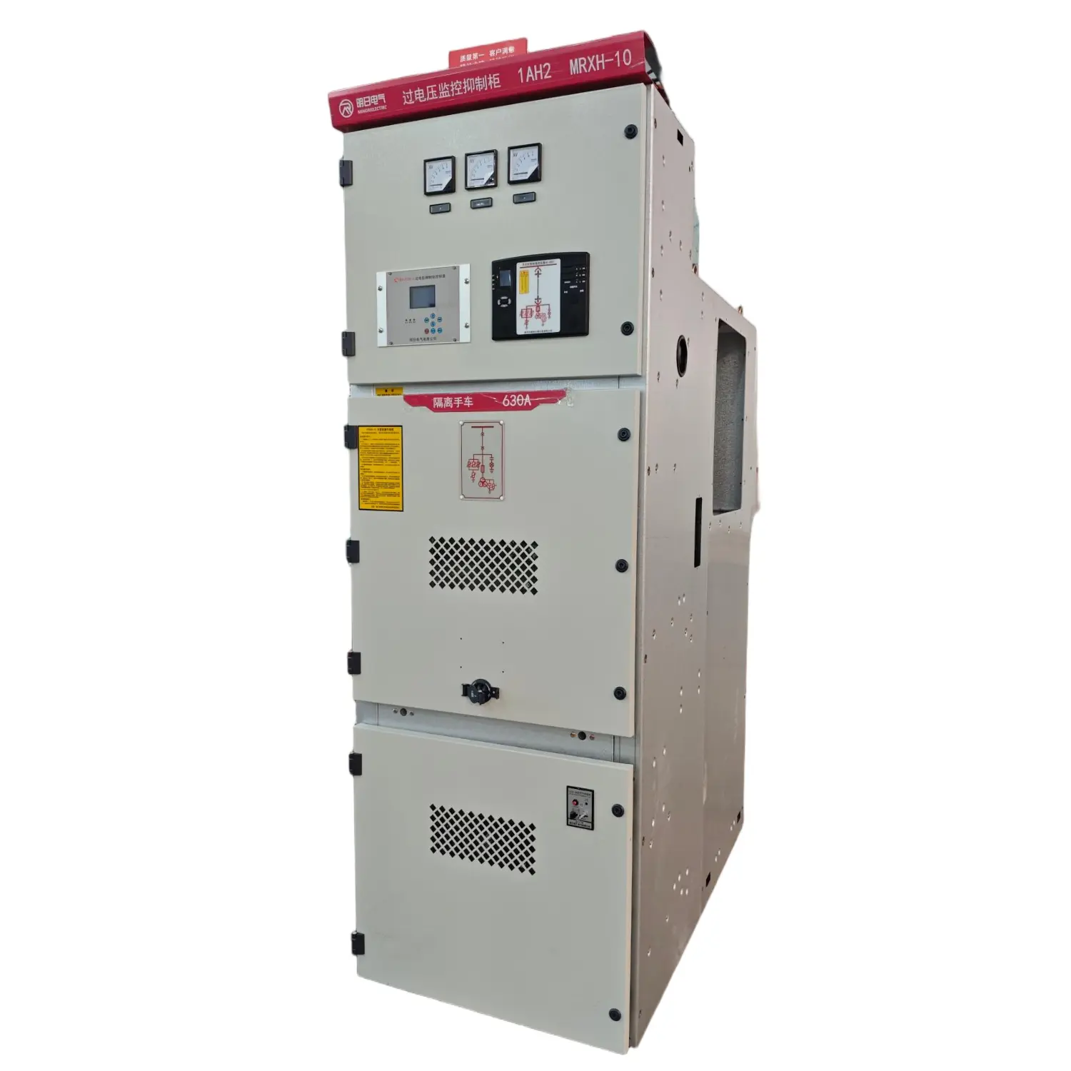


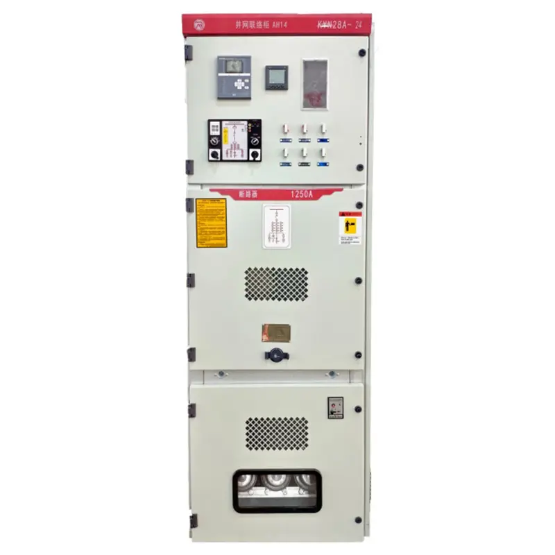
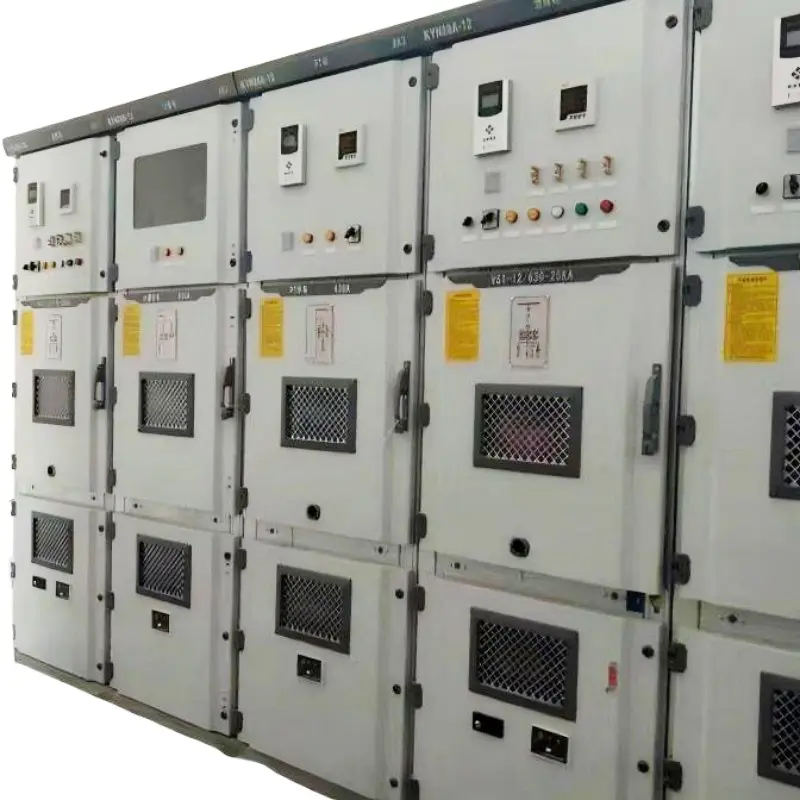
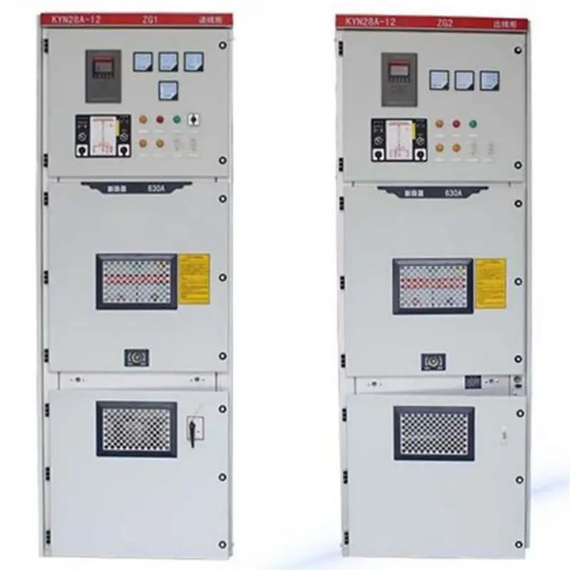
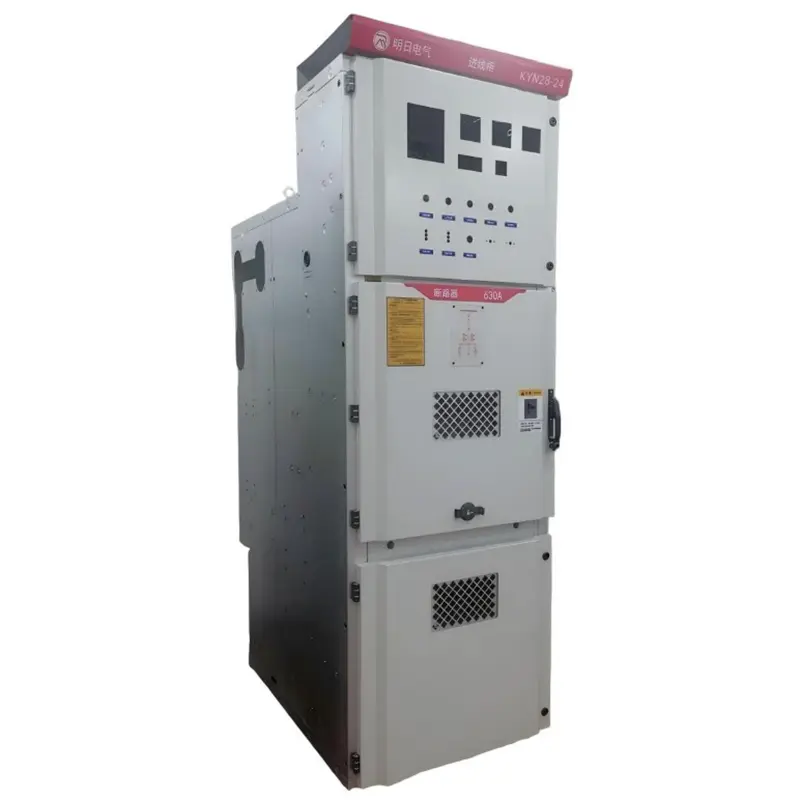
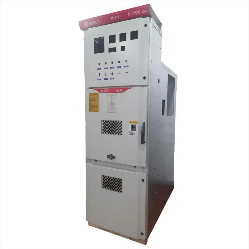
KYN28-24 Withdrawable Armored Metal-Enclosed Switchgear – Low Current Industrial Grade
Type Designation

| 1 | Armored Withdrawable Metal-Clad Switchgear |
| 2 | Withdrawable Type |
| 3 | Usage Conditions: (Indoor) |
| 4 | Design Serial Number |
| 5 | Rated Voltage (kV) |
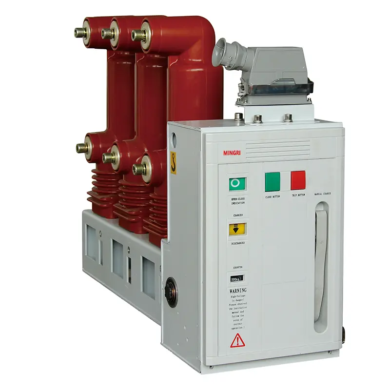
| 6 | Vacuum Circuit Breaker |
Technical Parameters
| Parameter | Unit | Value | ||
| Rated Voltage | kV | 24 | ||
| Rated Frequency | Hz | 50 | ||
| Rated Current of Circuit Breaker | A | 630,1250,1600,2000,2500,3150 | ||
| Rated Current of Switchgear | A | 630,1250,1600,2000,2500,3150 | ||
| Rated Dynamic Withstand Current (4s) | kA | 20,25,31.5 | ||
| Rated Peak Withstand Current | kA | 50,63,80 | ||
| Rated Short-Circuit Breaking Current | kA | 20,25,31.5 | ||
| Rated Short-Circuit Making Current (Peak) | kA | 50,63,80 | ||
| Rated Insulation Level | 1min Power Frequency Withstand Voltage | Pole-to-Pole & Pole-to-Ground | kV | 65 |
| Across Breaking Contacts | kV | 79 | ||
| Lightning Impulse Withstand Voltage | Pole-to-Pole & Pole-to-Ground | kV | 125 | |
| Across Breaking Contacts | kV | 145 | ||
| Protection Class | Enclosure: IP4X; IP2X when | |||
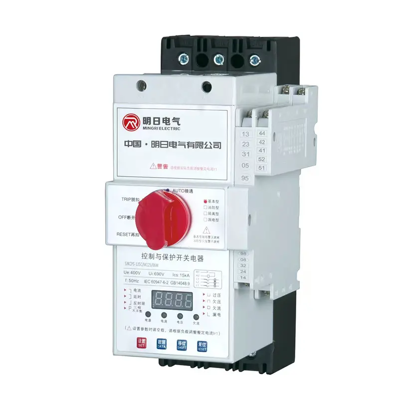
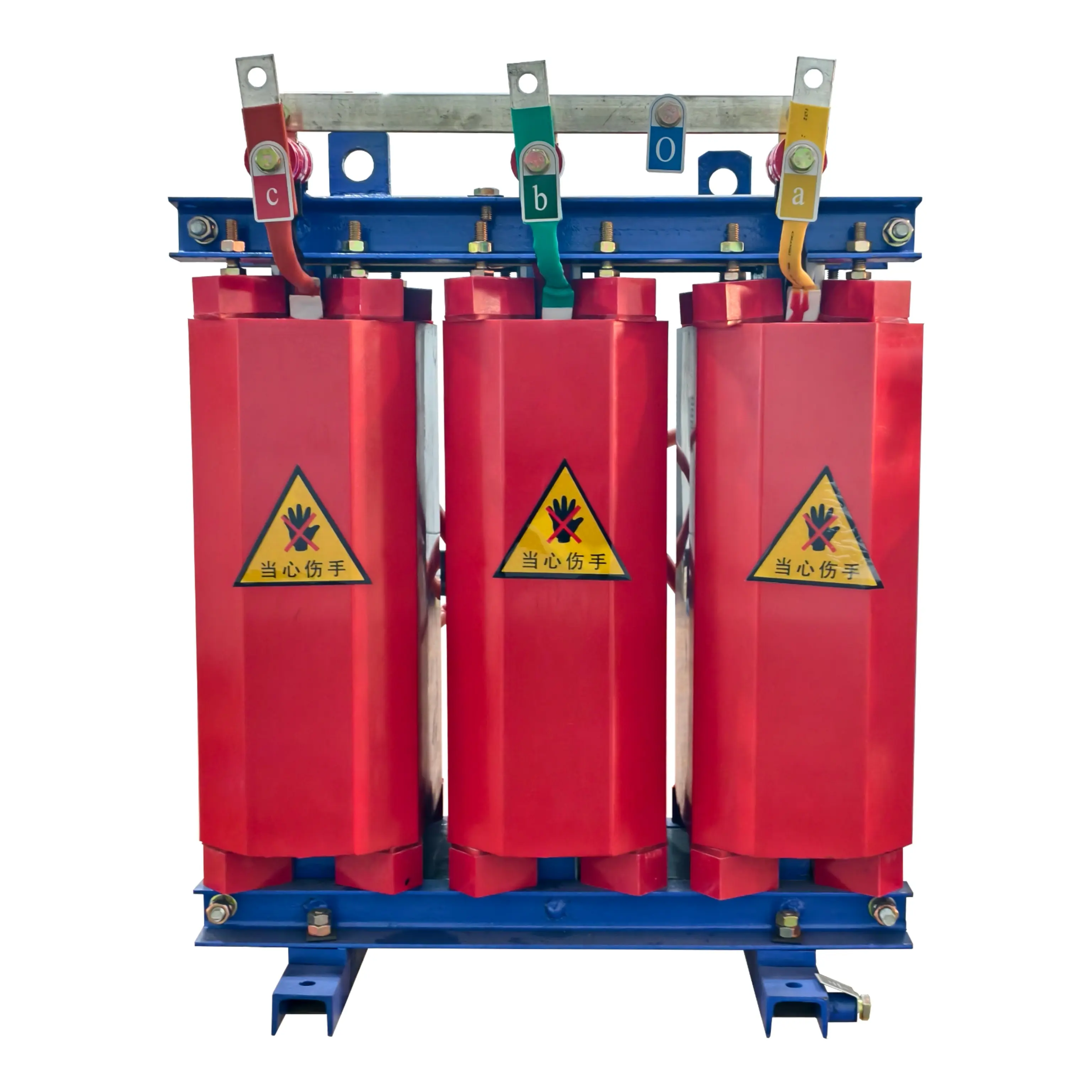
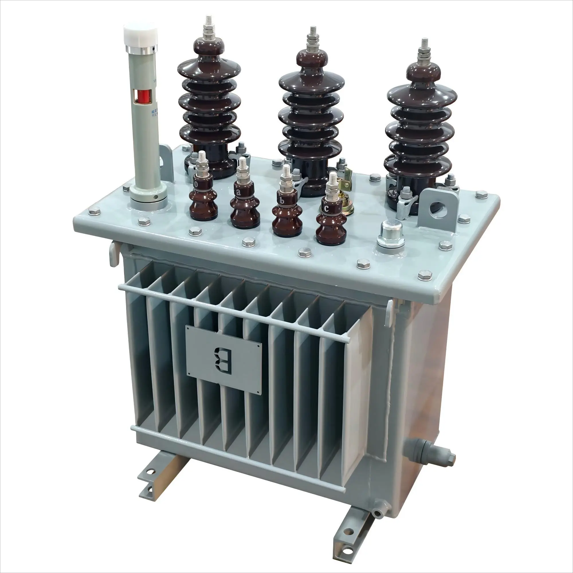
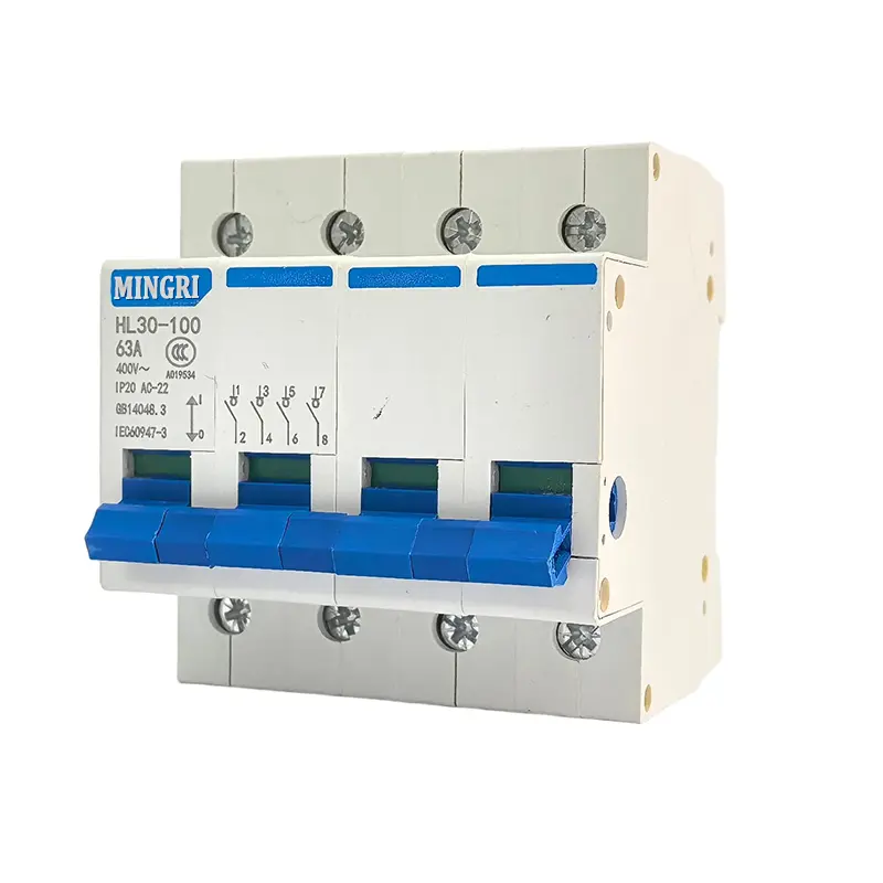
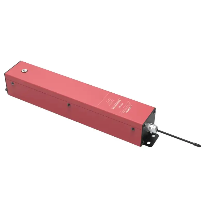
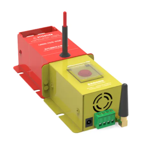
product Display
Installation Dimension Drawing
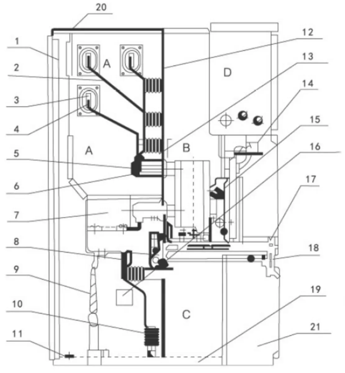
| A. Busbar Compartment | 10.Surge Arrester |
| B. Circuit Breaker Trolley Compartment | 11.Earthing Main Busbar |
| C. Cable Compartment | 12.Removable Partition |
| D. Relay & Instrument Compartment | 13.Shutter (Isolation Barrier) |
| 1. Enclosure | 14.Secondary Plug |
| 2. Branch Busbar | 15.Circuit Breaker Trolley |
| 3.Busbar Bushing | 16.Heating Device |
| 4.Main Busbar | 17.Removable Horizontal Partition |
| 5.Fixed Contact | 18.Earthing Switch Operating Mechanism |
| 6.Fixed Contact Housing | 19.Base Plate |
| 7.Current Transformer (CT) | 20.Pressure Relief Device |
| 8.Earthing Switch | 21.Control Wire Duct |
| 9.Cable |
Ordering Notice
Product operating site and special requirements:
1. Provide product ordering drawings, which should include wiring diagrams and indicate transformer capacity, main component model specifications, distribution branch circuits, and capacity
2. When it is necessary to configure electric energy metering and reactive power automatic compensation devices, the requirements for the configuration of the metering meter and transformer should be provided, and the capacity of the compensation capacitor should be indicated
3. Specify the requirements for surface treatment of the product