


 Claire
 Mr.Fu
Mr.Fu

 Claire
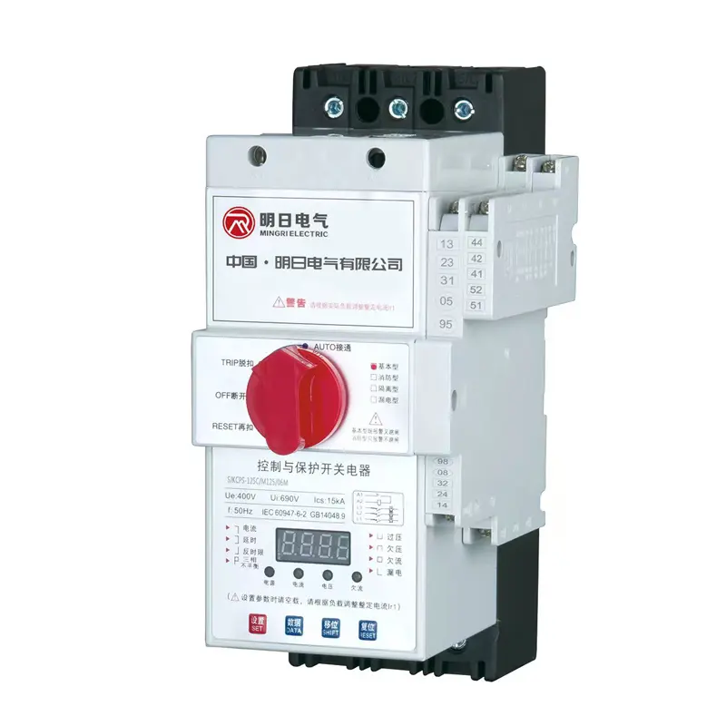


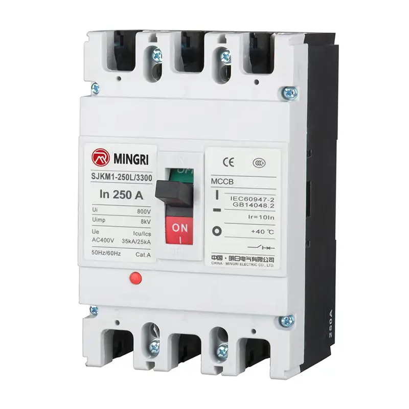

SJKM1 Moulded Case Circuit Breaker (MCCB) for Power Systems
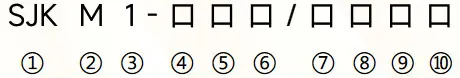
Type Designation
|
① |
Manufacturer Code |
|
② |
Molded Case Circuit Breaker Code |
|
③ |
Design Code |
|
④ |
Frame Size |
|
⑤ |
Short-Circuit Breaking Capacity Level 4 |
|
⑥ |
Operation method 3 |
|
⑦ |
Number of Poles 2 |
|
⑧ |
Trip Unit Method & File Code |
|
⑨ |
Function Code 1 |
|
⑩ |
Type code(See Table 1 for N-pole of four-pole,no code for three-pole) |
Notes:
1. There is no code for distribution circuit breakers; for motor - protection circuit breakers, use 2 to represent.
2. Number of poles: 2 for two - pole; 3 for three - pole; 4 for four - pole.
3. For handle - direct operation: use D to represent for power - distribution use, and use Z to represent for conversion - locking use.
4. For economy type: represent with E; for standard type: represent with M; for higher - reliability type: represent with H; for high - breaking type: represent with L.
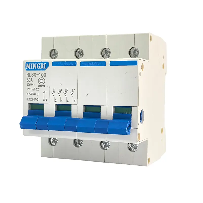
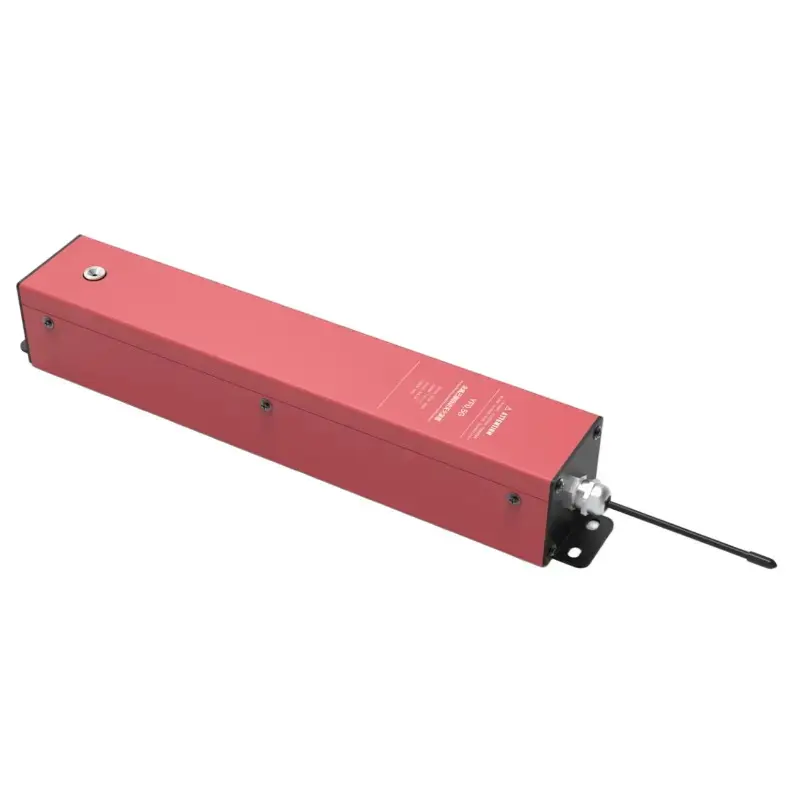
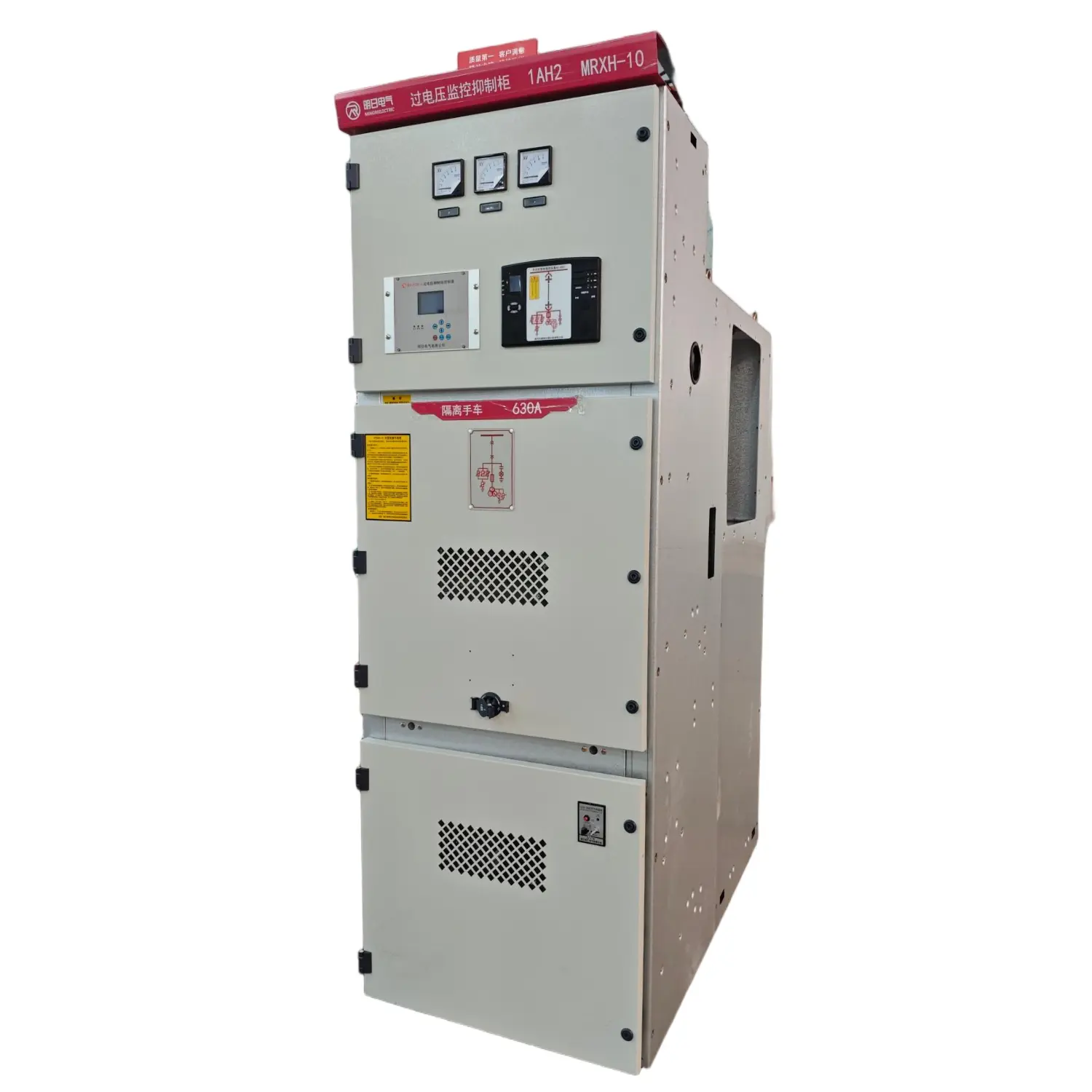
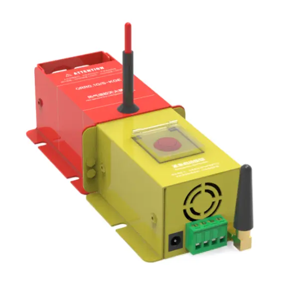
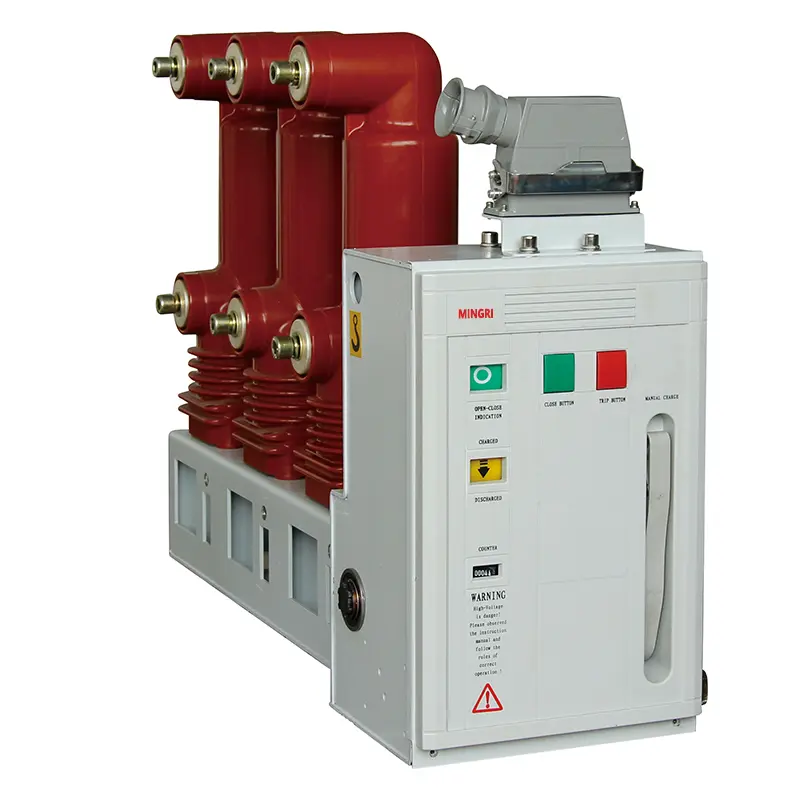
product Display


N - pole type code
|
Type Code |
Description |
|
Type A |
No over - current release element is installed on the N - pole, and the N - pole is always connected, and does not close and open together with the other three poles. |
|
Type B |
No over - current release element is installed on the N - pole, and the N - pole closes and opens together with the other three poles (the N - pole closes first and opens later). |
|
Type C |
An over - current release element is installed on the N - pole, and the N - pole closes and opens together with the other three poles (the N - pole closes first and opens later). |
|
Type D |
An over - current release element is installed on the N - pole, and the N - pole is always connected, and does not close and open together with the other three poles. |
Release Modes and Accessory Codes
|
Accessory Name |
Without Accessory |
Alarm Contact |
Shunt Release |
Auxiliary Contact |
Under - voltage Release |
Shunt Release Auxiliary Contact |
Two - group Auxiliary Contacts |
Shunt Release Under - voltage Release |
Auxiliary Contact Under - voltage Release |
|
|
Release Mode |
Instantaneous Code |
200 |
208 |
210 |
220 |
230 |
240 |
250 |
260 |
270 |
|
Release Mode |
Compound Code |
300 |
208 |
310 |
320 |
330 |
340 |
350 |
360 |
370 |
(Continued from the previous table)
|
Accessory Name |
Shunt Release Alarm Contact |
Auxiliary Contact Alarm Contact |
Under - voltage Release Alarm Contact |
Shunt Release Auxiliary Contact Alarm Contact |
Two - group Auxiliary Contact Alarm Contact |
Auxiliary Contact Under - voltage Release Alarm Contact |
|
|
Release Mode |
Instantaneous Code |
218 |
228 |
238 |
248 |
268 |
278 |
|
Release Mode |
Compound Code |
318 |
328 |
338 |
348 |
268 |
378 |
Notes:
1) 200 indicates the circuit breaker body with only an electromagnetic release; 300 indicates the circuit breaker body with thermal and electromagnetic releases.
2) For the two - level products SJKM1 - 125 and SJKM1 - 250, only 210, 310, 220, 320, 230, and 330 are available.
Normal Operating Conditions and Installation Conditions
◆ Ambient temperature: The circuit breaker can operate normally at an ambient temperature range of -5°C to +40°C (except for special orders).
◆ Altitude: The altitude of the installation site of the circuit breaker shall not exceed 2000m.
◆ Pollution degree: The pollution degree of the circuit breaker is Grade 3.
◆ Installation category: The installation category of the circuit breaker is Category III.
◆ Installation position: The circuit breaker can be installed horizontally, vertically, or flat, without reducing its electrical performance.
Main Parameters and Technical Performances
|
Circuit Breaker Model |
SJKM1-63 |
SJKM1-125 |
SJKM1-250 |
SJKM1-400 |
SJKM1-630 |
SJKM1-800 |
SJKM1-1250 |
||||||||||||
|
Pole Number |
3 |
4 |
3 |
2 |
4 |
3 |
2 |
4 |
3 |
4 |
3 |
4 |
3 |
4 |
3 |
4 |
|||
|
Rated Current In A |
10 16 2025 32 4050 63 |
16 20 25 32 40 50 63 80 100 125 |
100 125 140160 180 200225 250 |
225250315350400 |
400 500 630 |
630 700 800 |
80010001250 |
||||||||||||
|
Rated Insulation Voltage Ui (V) |
690 |
1000 |
1000 |
1000 |
1000 |
1000 |
1000 |
||||||||||||
|
Rated Impulse Withstand Voltage Uimp V |
6000 |
8000 |
|||||||||||||||||
|
Rated Working Voltage Ue V |
400 |
AC400/690 |
AC400/690 |
AC400/690 |
AC400/690 |
AC400/690 |
AC400/690 |
||||||||||||
|
Breaking Capacity Level |
L |
M |
L |
M |
H |
L |
M |
H |
L |
M |
H |
L |
M |
H |
H |
H |
|||
|
Ultimate Short-Circuit Breaking Capacity Icu (kA) (0-tCO) |
400V |
25 |
50 |
35 |
50 |
85 |
35 |
50 |
85 |
50 |
65 |
100 |
50 |
65 |
100 |
100 |
100 |
||
|
690V |
25 |
25 |
30 |
30 |
25 |
||||||||||||||
|
Service Short-Circuit Breaking Capacity Ics (kA) (0-tCOtCO) |
400V |
18 |
30 |
25 |
35 |
50 |
25 |
35 |
65 |
35 |
50 |
65 |
35 |
50 |
65 |
65 |
50 |
||
|
690V |
15 |
15 |
20 |
20 |
20 |
||||||||||||||
Appearance and Installation Dimensions
◆ Appearance and installation dimensions of the fixed - type front - connected and rear - connected wiring
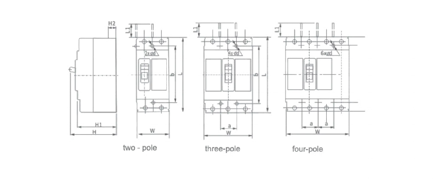
◆ Appearance and installation dimensions of fixed - type front and rear wiring
|
model |
Number |
Overall dimensions( mm) |
Mounting Dimensions(mm) |
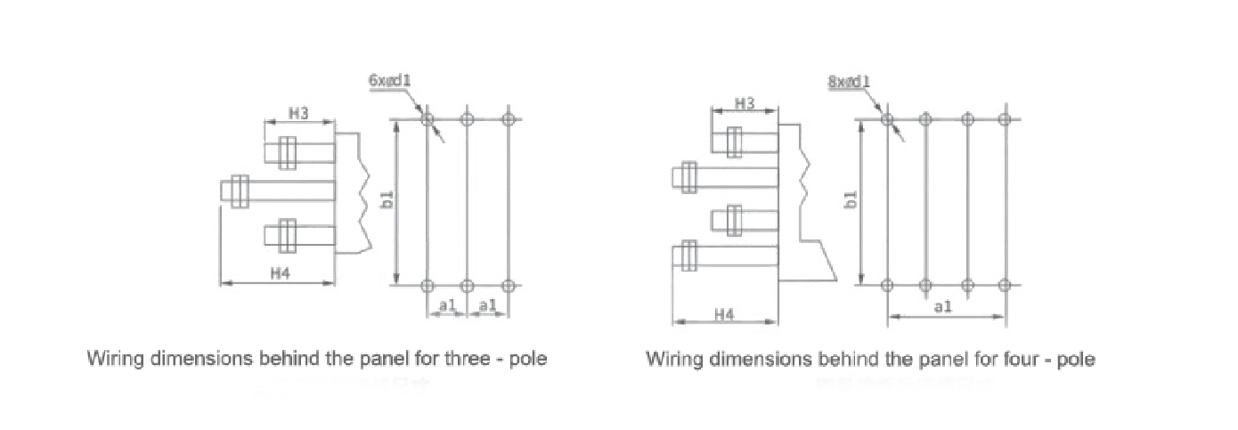
Dimensions for Rear Terminal Wiring(mm) |
|||||||||||||||
|
L |
L1 |
W |
H |
H1 |
H2 |
a |
b |
φd |
al |
b1 |
d1 |
H3 |
H4 |
||||||
|
SJKM1-63L |
3 |
135 |
21 |
76 |
88 |
72 |
19 |
25 |
117 |
4 |
25 |
117 |
18 |
52 |
75 |
||||
|
SJKM1-63M |
97 |
82 |
28 |
||||||||||||||||
|
SJKM1-63 |
4 |
103 |
|||||||||||||||||
|
SJKM1-125L |
150 |
51 |
92 |
86 |
68 |
24 |
30 |
129 |
4.5 |
30 |
132 |
22 |
65 |
100 |
|||||
|
SJKM1-125M |
3 |
104 |
86 |
23 |
|||||||||||||||
|
SJKM1-125H |
|||||||||||||||||||
|
SJKM1-125 |
2 |
65 |
--- |
||||||||||||||||
|
4 |
122 |
30 |
|||||||||||||||||
|
SJKM1-250L |
165 |
64 |
107 |
108 |
87 |
25 |
35 |
126 |
5.5 |
35 |
144 |
24 |
70 |
110 |
|||||
|
SJKM1-250M |
3 |
165 |
107 |
124.5 |
104 |
24.5 |
|||||||||||||
|
SJKM1-250H |
|||||||||||||||||||
|
SJKM1-250 |
2 |
75 |
-- |
||||||||||||||||
|
4 |
142 |
||||||||||||||||||
|
SJKM1-400 |
3 |
257 |
105 |
149 |
150 |
100 |
36.5 |
44 |
195 |
6.5 |
44 |
225 |
32 |
70 |
120 |
||||
|
4 |
198 |
||||||||||||||||||
|
SJKM1-630 |
3 |
270 |
118 |
182 |
155 |
108 |
41 |
58 |
200 |
7 |
58 |
234 |
40 |
70 |
120 |
||||
|
4 |
240 |
||||||||||||||||||
|
SJKM1-800 |
3 |
282 |
102 |
210 |
158 |
103 |
34.5 |
70 |
243 |
7 |
70 |
243 |
48 |
70 |
125 |
||||
|
4 |
280 |
||||||||||||||||||
|
SJKM1-1250 |
3 |
406 |
104 |
210 |
190 |
140.5 |
58.5 |
70 |
375 |
10 |
- |
- |
- |
||||||
|
手柄 |
H |
W |
Protrusion in the middle |
L |
W |
H |
|||||||||||||
|
63 |
17 |
13.5 |
63 |
44 |
22 |
5.5 |
|||||||||||||
|
125 |
19 |
13 |
125 |
51 |
23 |
5.5 |
|||||||||||||
|
250 |
22 |
12.5 |
250 |
52 |
23 |
4 |
|||||||||||||
|
400 |
43.5 |
33.5 |
400 |
89.5 |
65 |
7 |
|||||||||||||
|
630 |
44 |
33.5 |
630 |
90 |
65.5 |
7 |
|||||||||||||
|
800 |
40 |
33.5 |
800 |
105 |
61 |
5 |
|||||||||||||
|
1250 |
51 |
41 |
1250 |
100 |
78 |
16 |
|||||||||||||
◆ Appearance and installation dimensions of the plug - in type front - connected wiring
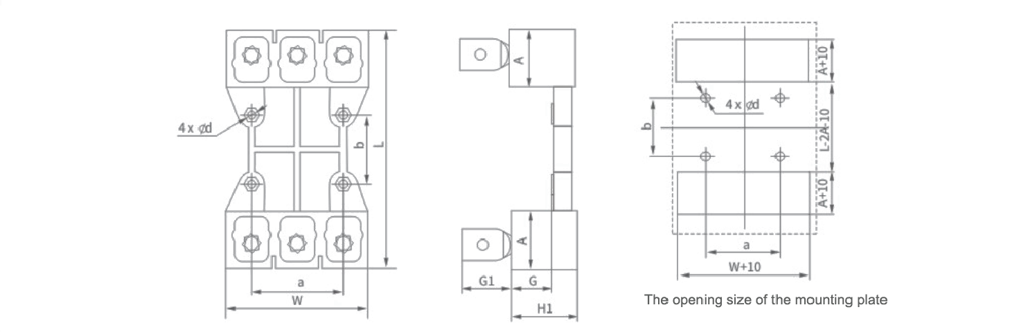
◆ Appearance and installation dimensions of plug - in type rear - panel wiring
|
Model |
W |
L |
A |
H1 |
G |
G1 |
a |
b |
d |
|
SJKM1-63 |
75 |
135 |
18 |
28 |
17 |
15 |
50 |
60 |
6 |
|
SJKM1-125 |
92 |
170 |
38 |
50 |
33 |
28 |
60 |
56 |
6.5 |
|
SJKM1-250 |
107 |
186 |
46 |
50 |
33 |
40 |
70 |
54 |
7 |
|
SJKM1-400 |
144 |
280 |
50 |
60 |
40 |
48 |
88 |
143 |
9 |
|
SJKM1-630 |
182 |
300 |
65 |
60 |
40 |
53 |
100 |
123 |
9 |
|
SJKM1-800 |
212 |
298 |
57 |
100 |
43 |
129 |
140 |
143 |
9 |
◆ Outline and Installation Schematic Diagram of Withdrawable Device
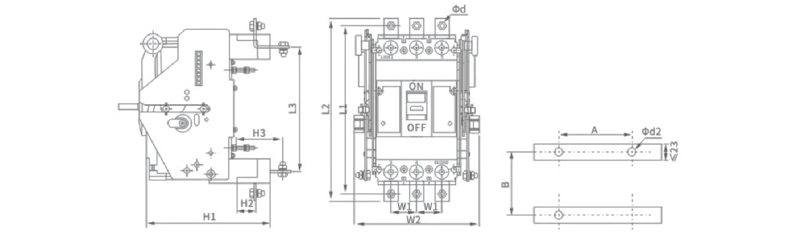
◆ Outline and Installation Dimensions of Withdrawable Device
|
Model |
pole |
overall dimensions |
installation dimensions |
||||||||||
|
L1 |
L2 |
L3 |
H1 |
H2 |
H3 |
W1 |
W2 |
φd1 |
A |
B |
φd2 |
||
|
SJKM1-400/M |
3P |
310 |
339 |
203 |
253 |
17.5 |
77 |
48 |
223 |
φ11 |
96 |
134 |
φ6.5 |
|
4P |
310 |
339 |
203 |
253 |
17.5 |
77 |
48 |
271 |
φ11 |
144 |
134 |
φ6.5 |
|
|
SJKM1-630/M |
3P |
341 |
381 |
211 |
282 |
17.5 |
92 |
58 |
253 |
φ13 |
116 |
140 |
φ6.5 |
|
4P |
341 |
381 |
211 |
282 |
17.5 |
92 |
58 |
311 |
φ13 |
174 |
140 |
φ6.5 |
|
|
SJKM1-800/M |
3P |
367 |
410 |
241 |
238 |
26 |
73 |
70 |
289 |
φ13 |
140 |
131 |
φ6.5 |
|
4P |
367 |
410 |
241 |
238 |
26 |
73 |
70 |
359 |
φ13 |
210 |
131 |
φ6.5 |
|