


 Claire
 Mr.Fu
Mr.Fu

 Claire
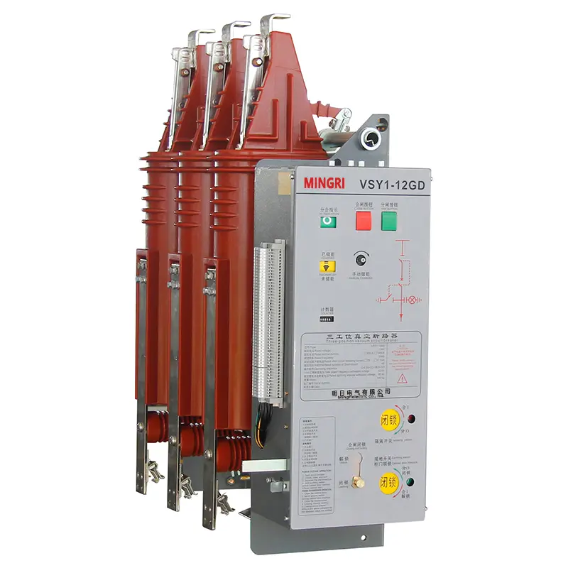
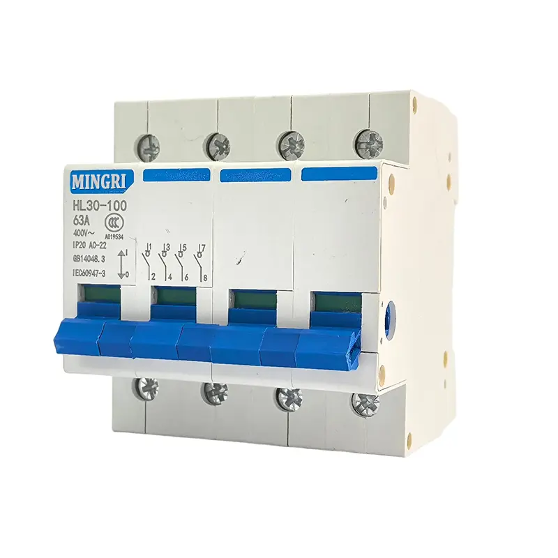
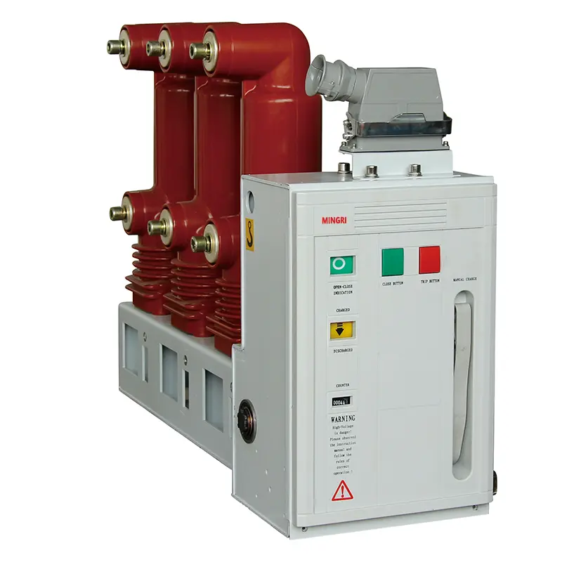


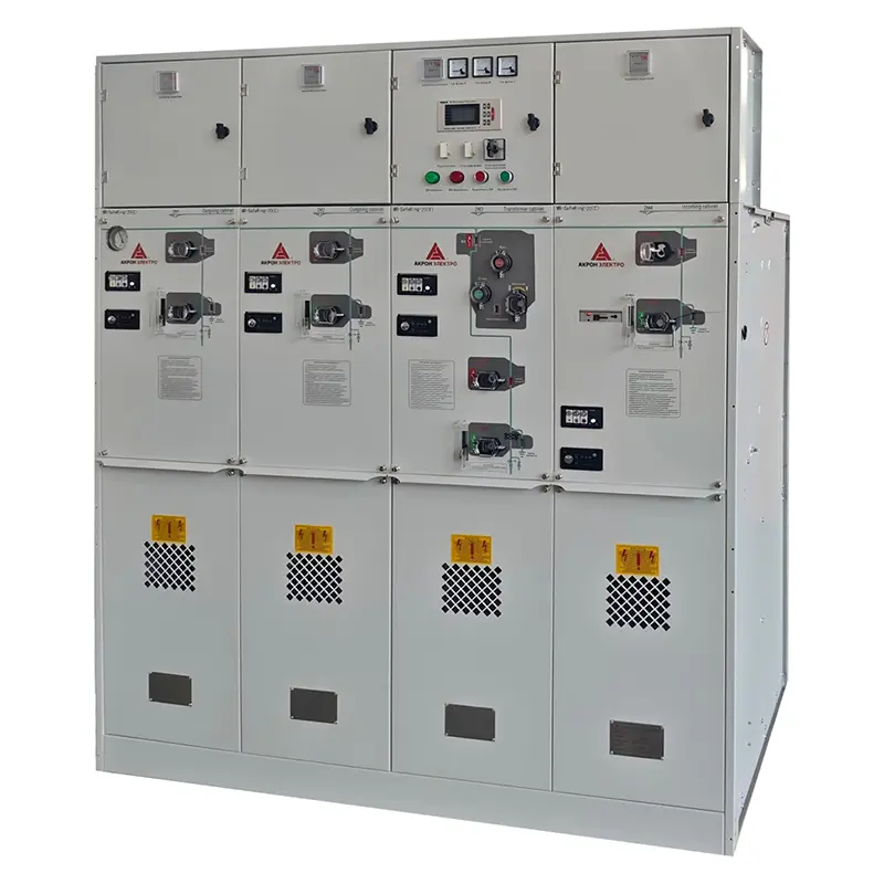
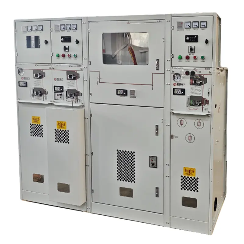
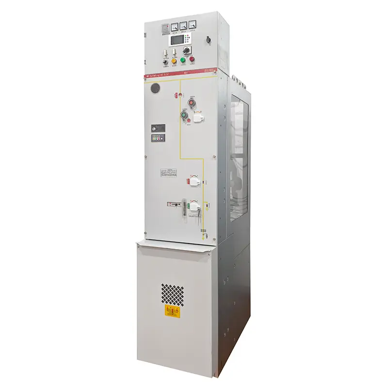
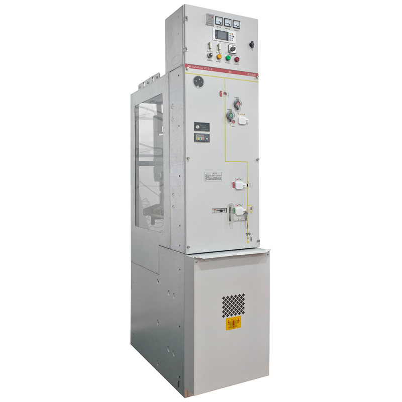
SafeRing-40.5 Gas Insulated Ring Main Unit (RMU) -SF6 Sealed Switchgear
Type Designation
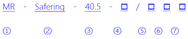
| 1 | Manufacturer Code |
| 2 | Model Type |
| 3 | Rated Voltage: 40.5 Rated voltage 40.5KV |
| 4 | Cabinet Type: C: Load Switch Cabinet; F: Fuses Switchgear Cabinet; V: Vacuum Circuit Breaker Cabinet; M: Measuring cabinet; SV,SL,Bus Sectionalizing Switchgear; PT: PT Cabinet(Co-enclosure cabinet composed of any combination of C,F,V,S,VSL.) |
| 5 | Rated Current: 2500 Rated Current 2500A; 3150 Rated Current 3150A |
| 6 | Expansion Type: I: Left Extension; D: Right Extension; ID: Both Sides; Blank: extendable |
| 7 | Cable entry/exit method: L: Left; R: Right; LR: Both; Blank:Front |
Technical Parameters
| Name | Unit | Parameter | ||||
| Rated voltage | kV | 12 | 40.5 | |||
| Rated current | A | 1250-3150 | 1250-2500 | |||
| Rated frequency | Hz | 50 | ||||
| Rated short-time withstand current | k/Vs | 25,31.5 | ||||
| Rated peak withstand current | kA | 63,80 | ||||
| Rated short-circuit current duration | s | 4 | ||||
| Rated short-circuit breaking current | kA | 25,31.5 | ||||
| Rated short-circuit making current | kA | 63,80 | ||||
| Duration of arcing | S | 0.5 | ||||
| Mechanical life | Circuit breaker | Times | 2000 | 10000 | ||
| Isolating switch | 3000 | |||||
| Earthing switch | 3000 | |||||
| Electrical life of circuit breaker | Times | 30 | ||||
| Rated inflation pressure(20℃ gauge pressure) | MPa | 0.05 | ||||
| Minimum functional pressure(20℃ gauge pressure) | 0.03 | |||||
| Annual leakage rate of SF₆gas | ≤0.5% | |||||
| Rated insulation level | Rated power frequency 1min withstand voltage(effective value) | Phase to phase | kV | 42 | 95 | |
| Isolation fracture,vacuum fracture | 48 | 118 | ||||
| Rated lightning impulse withstand voltage(peak value) | Phase to phase | 75 | 185 | |||
| Isolation fracture,vacuum fracture | 85 | 215 | ||||
| Auxiliary control circuit | Rated voltage | V | DC:110,220 AC:110,220 | |||
| 1min power frequency withstand voltage | 2000 | |||||
| Cabinet protection grade | Cabinet shell | IP4X | ||||
| Inflatable compartment | - | IP65 | ||||
| Category of loss of operation continuity | - | LSC2B | ||||
| Temperature rise test | A | 1.1lr | ||||
| Main circuit resistance | 1250 | μΩ | 85 | 100 | ||
| 2000 | 65 | |||||
| 2500 | 60 | 60 | ||||
| 3150 | 50 | |||||
| Partial discharge | Test voltage | kV | 1.1×12/√3 | 1.1X40.5/√3 | ||
| Single insulating element | pC | ≤3 | ||||
| Complete machine | ≤50 | |||||
| Service life | Year | ≥30 | ||||
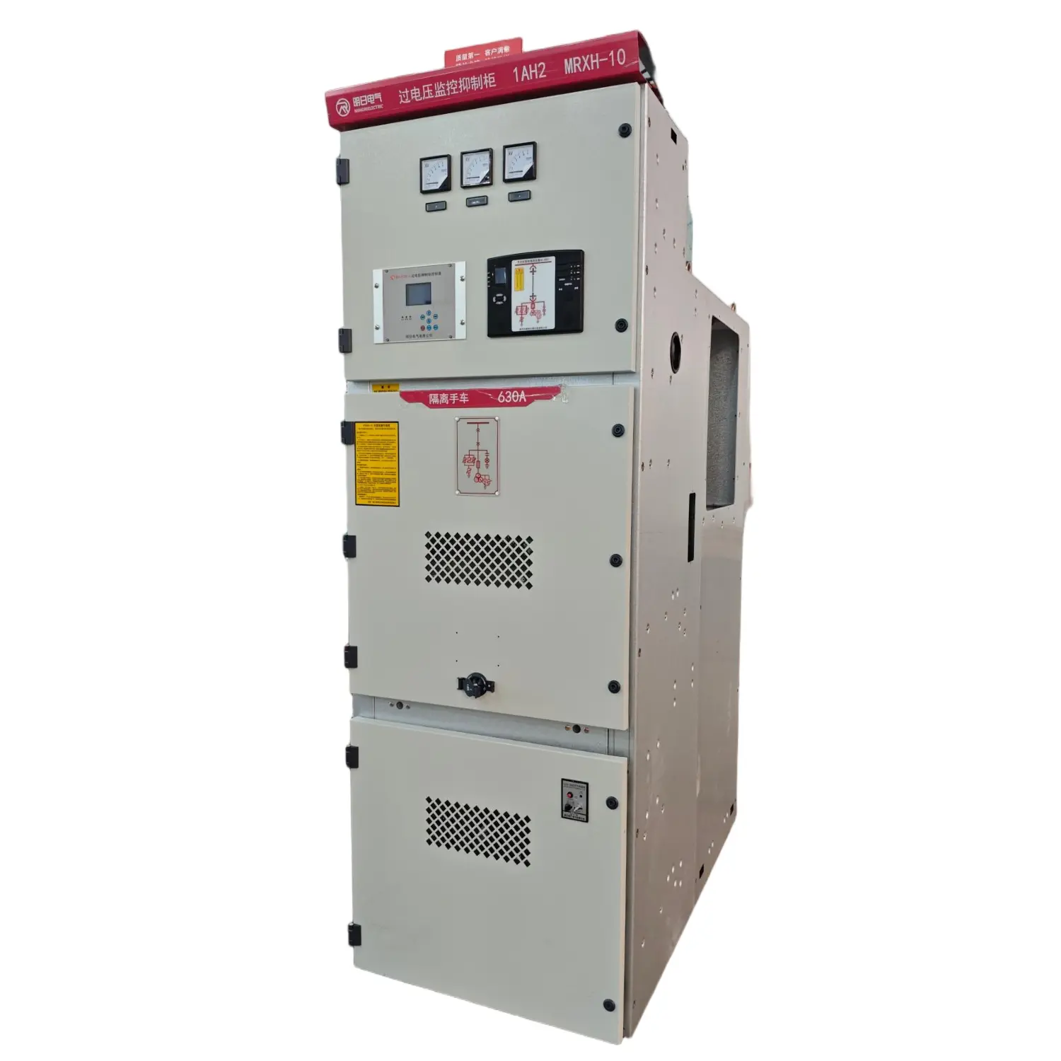
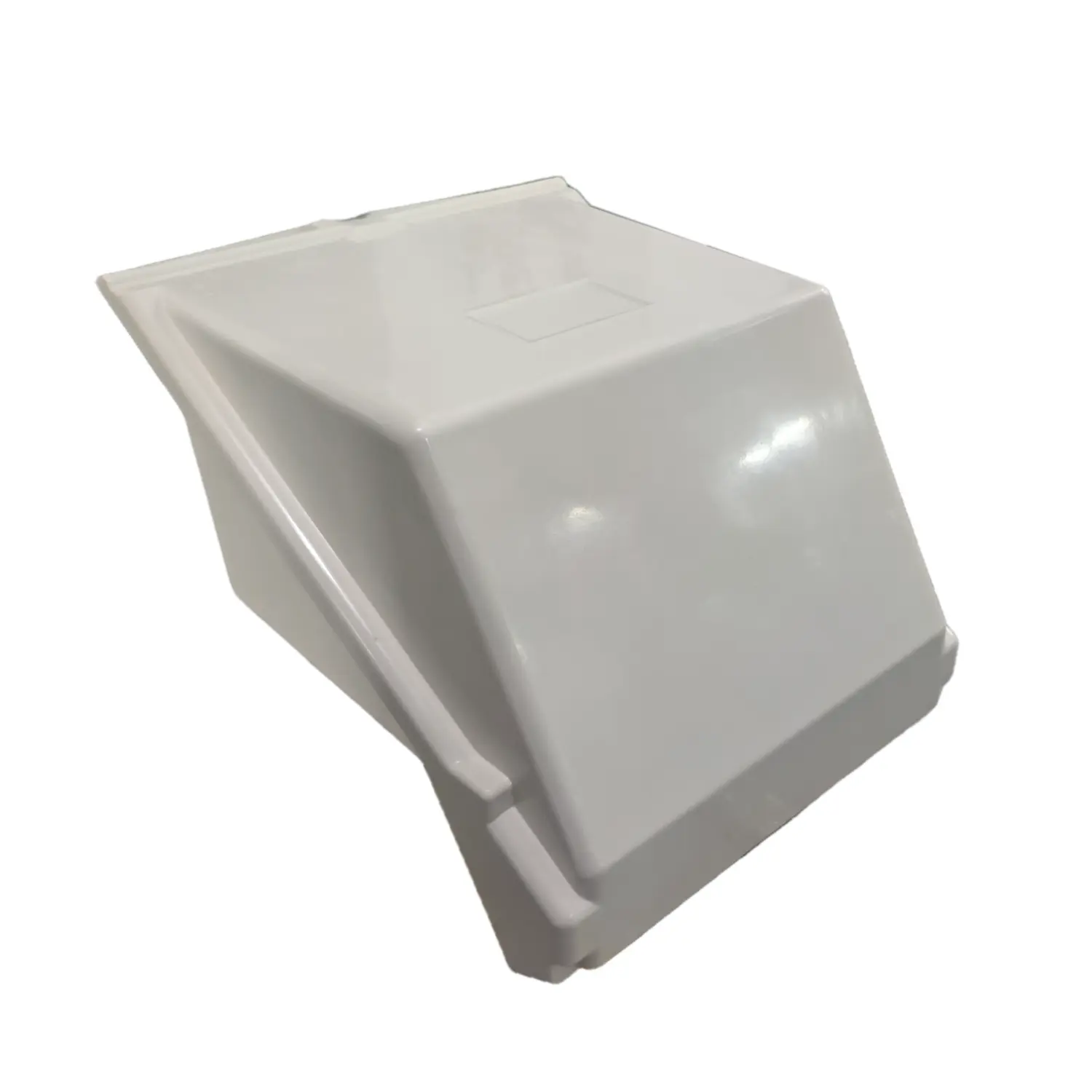
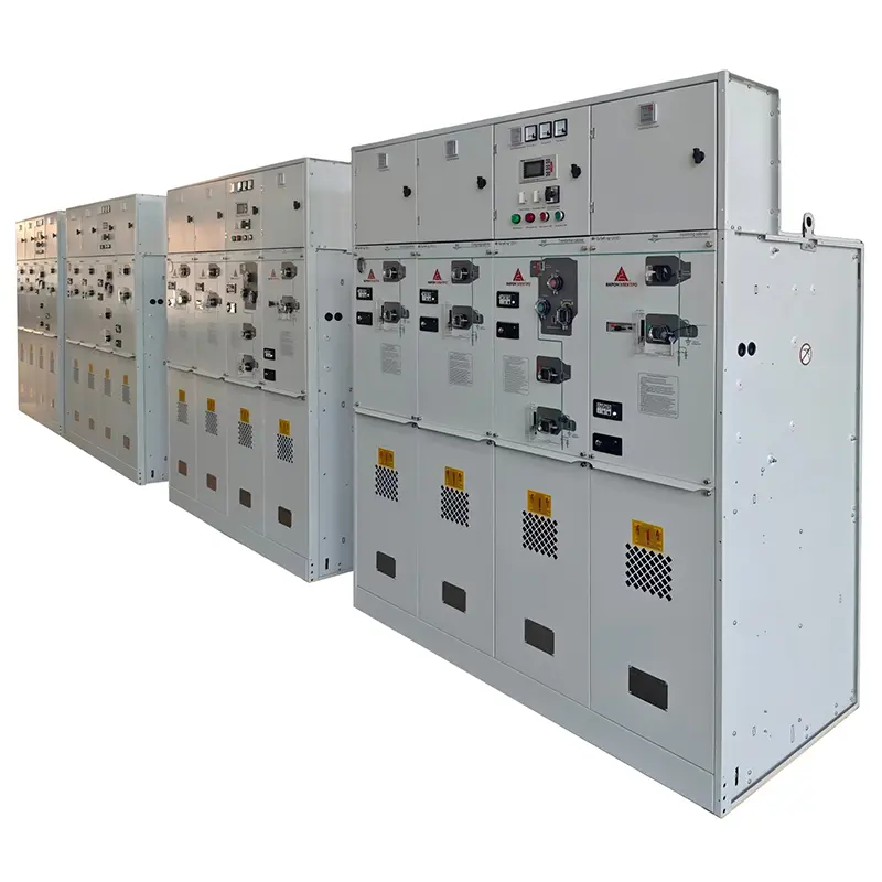
product Display
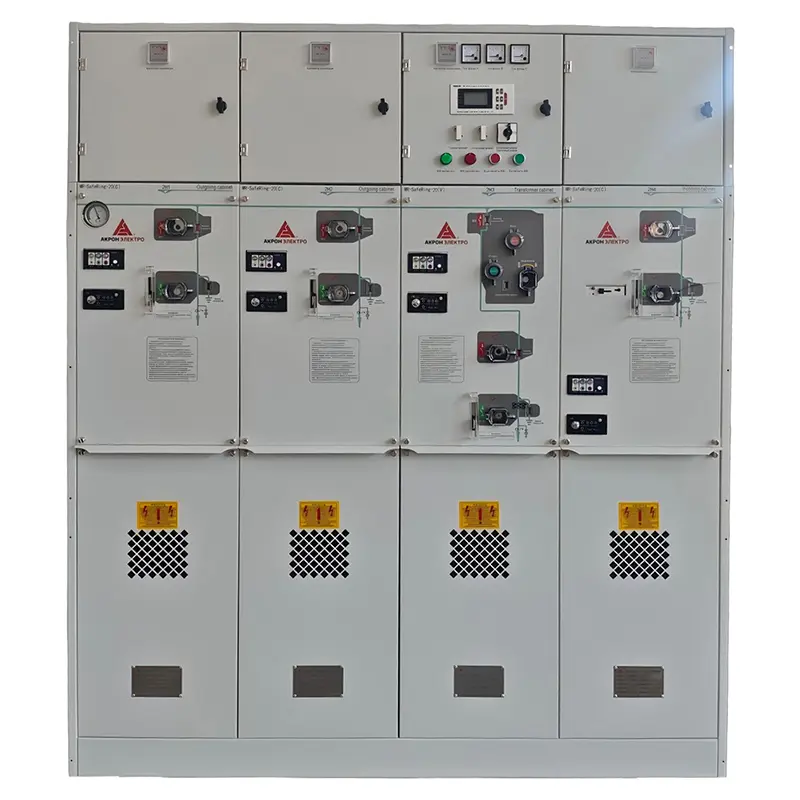
Outline and structure diagram of switch cabinet
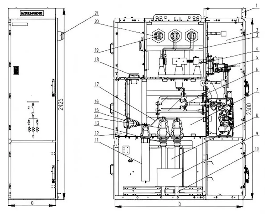
| 1.Small bus room | 11.CM-35 arrester |
| 2.Instrument room | 12.Pressure release channel |
| 3.Inflatable compartment of main bus | 13.Cable plug |
| 4.Station disconnector | 14.Cable socket |
| 5.Operating mechanism room | 15.Test socket plug |
| 6.Circuit breaker | 16.Test socket |
| 7.Inflatable compartment of circuit breaker | 17.Branch bus |
| 8.Cable chamber | 18.Pressure relief device |
| 9.Current transformer | 19.Main bus |
| 10.Cable | 20.Bus coupler socket |
| 21.Bus coupler | |
| Note: a(cabinet width): 600mm,800mm; b(cabinet depth): 12kV depth is 1420; The depth of 40.5kV is 1620. |
|
Ordering Notice
Product operating site and special requirements:
1. Provide product ordering drawings, which should include wiring diagrams and indicate transformer capacity, main component model specifications, distribution branch circuits, and capacity
2. When it is necessary to configure electric energy metering and reactive power automatic compensation devices, the requirements for the configuration of the metering meter and transformer should be provided, and the capacity of the compensation capacitor should be indicated
3. Specify the requirements for surface treatment of the product