


 Claire
 Mr.Fu
Mr.Fu

 Claire
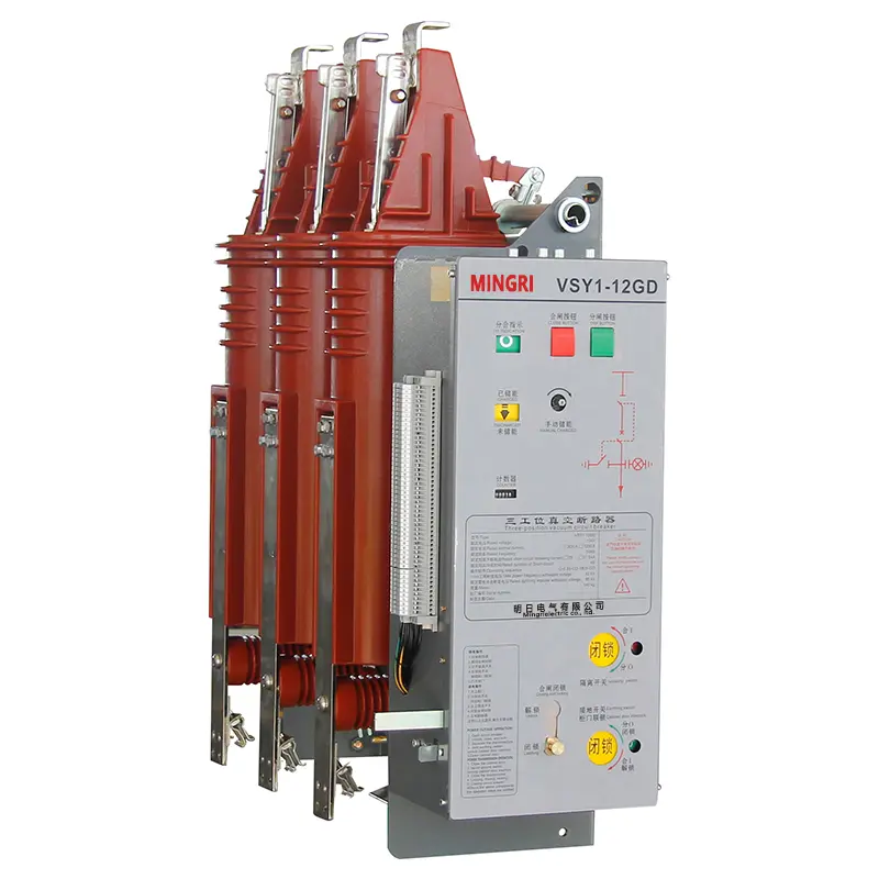
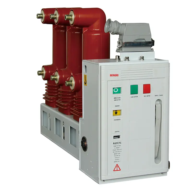

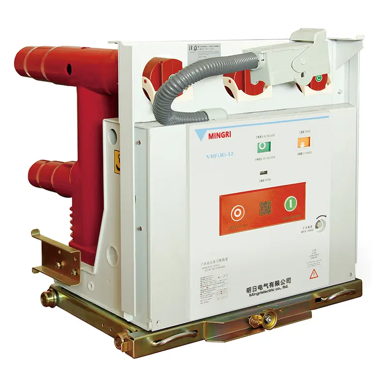
VBF(R)-12 Center-mounted fixed vacuum load switch-fuse combination
Type Designation

| 1 | Vacuum Load Break Switch |
| 2 | Fuse |
| 3 | Rated Voltage (kV) |
| 4 | Operation Mode: T represents Spring-operated |
| 5 | Rated Current (A) |
| 6 | Rated Short-circuit Breaking Current (kA) |
| 7 | Operating Voltage Category |
| 8 | Operating Voltage (V) |
| 9 | Pole Pitch / Phase Spacing (mm) |
| 10 | Phase Spacing (mm) |
| Example: VBF(R)-12/T125-50-AC220-275-210 It means ordering a combined apparatus for 800mm cabinet width, with a rated voltage of 12kV, rated current of 125A, short-circuit breaking current of 50kA, operating voltage AC220V, phase spacing of 275mm, and contact gap (pole pitch) of 210mm. |
|
Technical Parameters
Mechanical Characteristics
| No. | Item | Unit | Parameters | |
| 1 | Contact Gap | mm | 8-10 | |
| 2 | Contact Pressure,Spring Travel | mm | 3~5 | |
| 3 | Phase-to-phase Center Distance | mm | 150/210/275 | |
| 4 | Opening/Closing Asynchronism | ms | ≤2 | |
| 5 | Contact Bounce Time (during closing) | ms | ≤3 | |
| 6 | Average Closing Speed | m/s | 0.4~0.8 | |
| 7 | Average Opening Speed | m/s | 1.0-1.4 | |
| 8 | Closing Time (at rated operating voltage) | ms | ≤60 | |
| 9 | Opening Time (at rated operating voltage) | ms | ≤30 | |
| 10 | Main Circuit Resistance | μΩ | ≤250 | |
| 11 | Permissible Wear Thickness of Moving/Fixed Contacts | ms | 1-3 | |
Technical Parameters
| No. | Name | Unit | Parameters | |
| VBF-12/T630-20 Vacuum Load Break Switch |
VBFR-12/T125-50 Vacuum Load Break Switch-Fuse Combination Apparatus |
|||
| 1 | Rated Voltage | kV | 12 | 12 |
| 2 | Power Frequency Withstand Voltage (phase-to-phase, phase-to-earth) | kV | 42 | 42 |
| 3 | Lightning Impulse Withstand Voltage (phase-to-phase, phase-to-earth) | kV | 75 | 75 |
| 4 | Rated Current | A | 630 | 125(Fuse) |
| 5 | Rated Short-circuit Breaking Current | kA | - | 50(Fuse) |
| 6 | Rated Short-time Withstand Current | kA | 20 | - |
| 7 | Rated Peak Withstand Current | kA | 50 | - |
| 8 | Rated Short-circuit Making Current | kA | 50 | |
| 9 | Rated Cable Charging Breaking Current | A | 16 | - |
| 10 | Rated Transfer Current | A | - | 3150 |
| 11 | No-load Transformer Switching | kVA | 1250 | |
| 12 | Electrical Endurance | time | 10000 | |
| 13 | Partial Discharge Level | PC | ≤5 | |
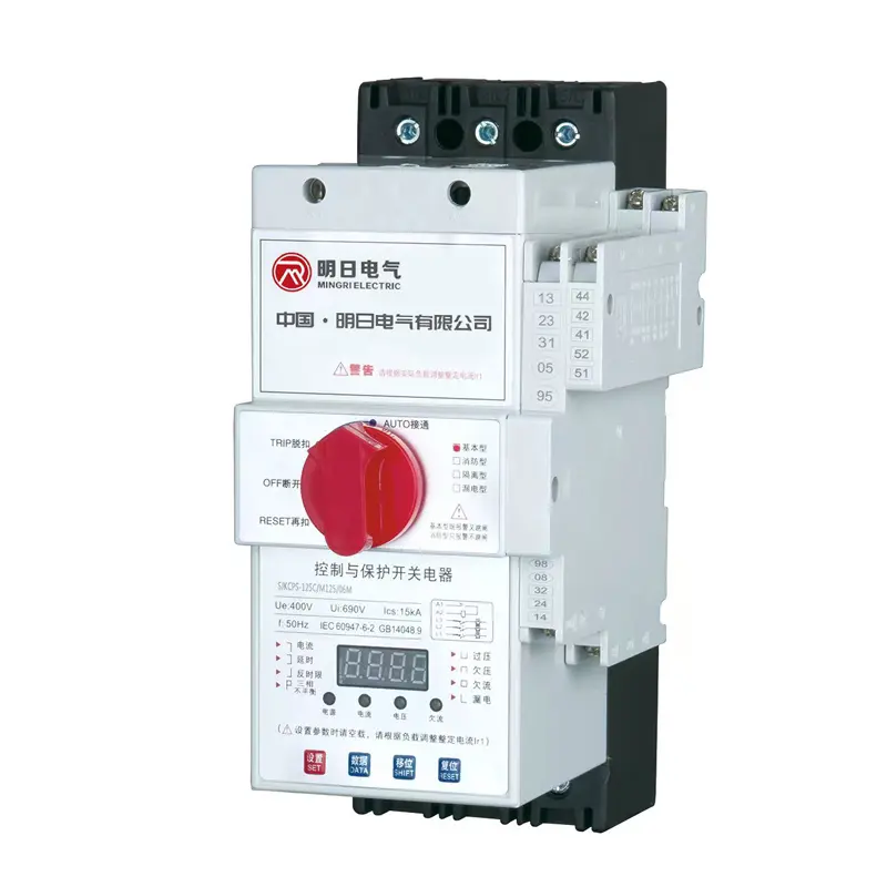
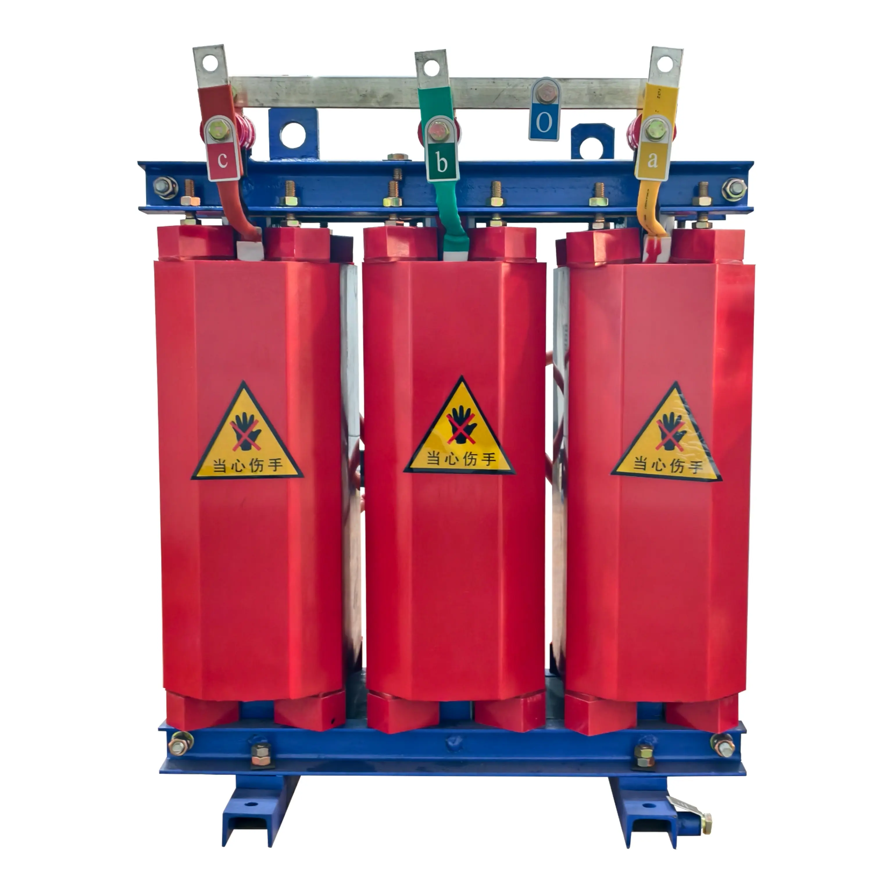
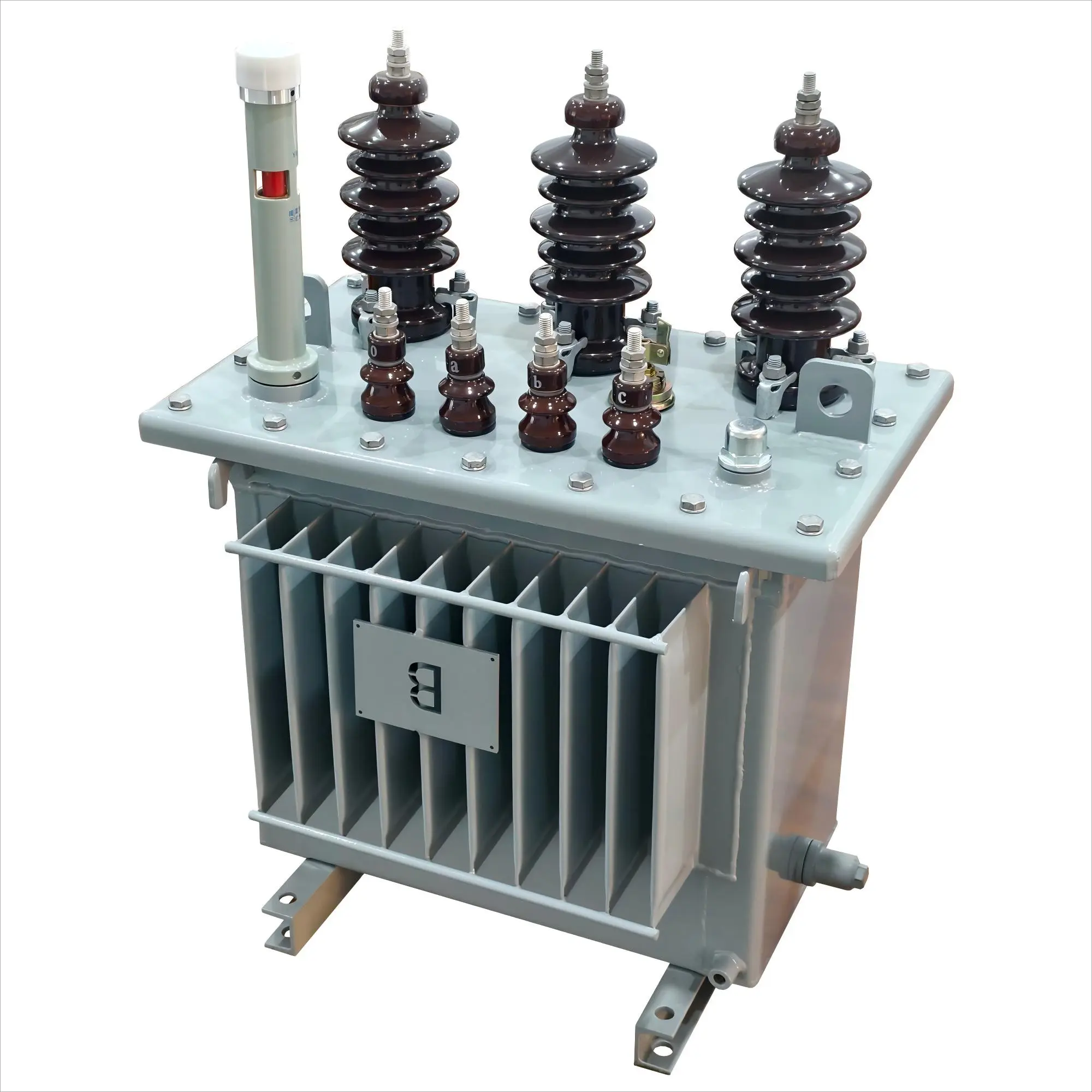
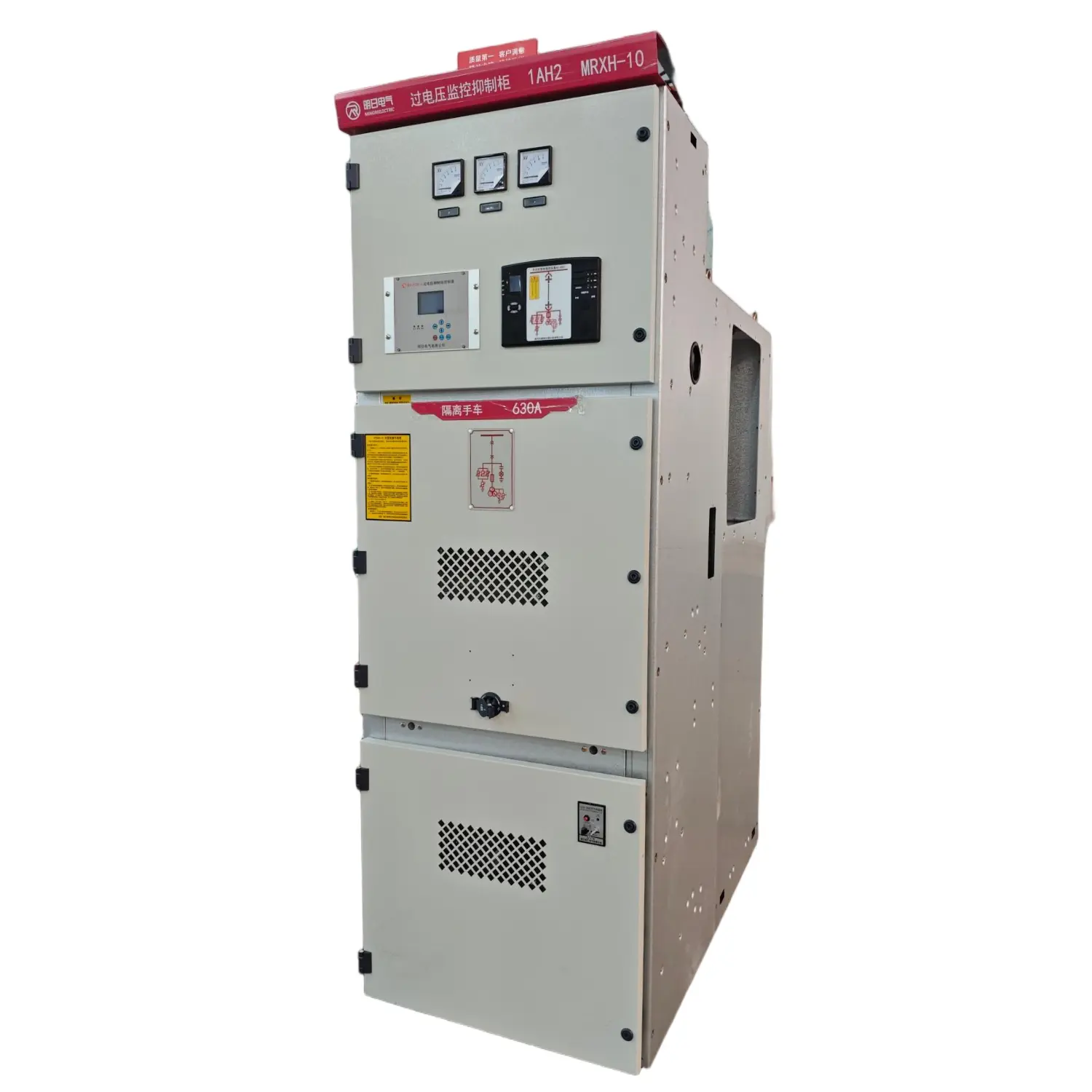
product Display


Installation and Overall Dimensions
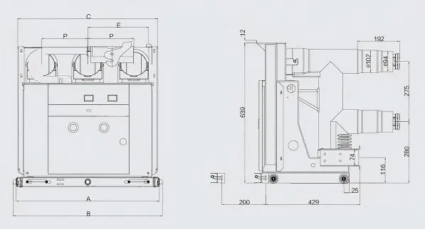
| Cabinet Width (Unit:mm) | P (Unit:mm) | A (Unit:mm) | B (Unit:mm) | C (Unit:mm) | E (Unit:mm) | Weight (Unit:kg) |
| 650 | 150 | 500 | 530 | 490 | 203 | 120 |
| 800 | 210 | 650 | 680 | 640 | 278 | 140 |
| 1000 | 275 | 850 | 880 | 840 | 378 | 160 |
Schematic Diagram of Vacuum Switch Application Solution

Schematic Diagram of Vacuum Switch Dimensions
◆Left: Schematic Diagram of Recommended Installation Dimensions for Vacuum Switch and Switchgear Coordination
◆Right: Schematic Diagram of Chassis Earthing (Grounding) Device Dimensions
