


 Claire
 Mr.Fu
Mr.Fu

 Claire

W1 ACB intelligent universal circuit breaker
Type Designation

| 1 | Enterprise code |
| 2 | Jniversal circuit breaker |
| 3 | Design serial number |
| 4 | Rated current of circuit breaker frame level |
| 5 | Numberof poles: 4-pole marked as 4, no marking for 3-pole |
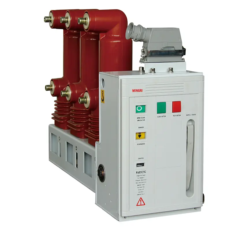
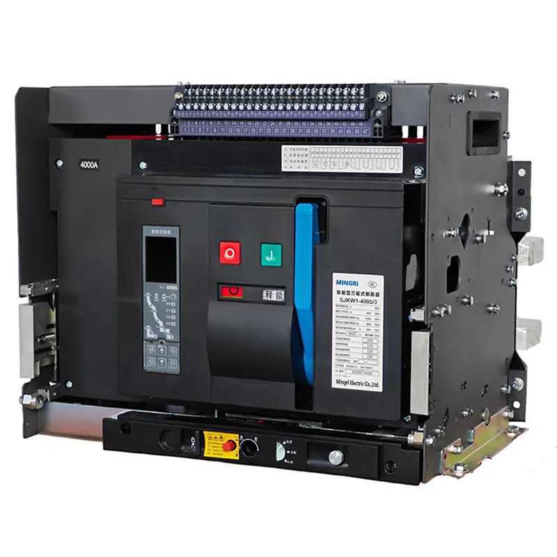
product Display


Product Structure Diagram
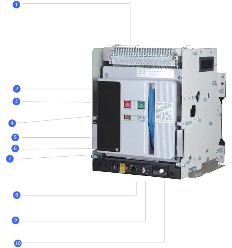
① Secondary Circuit Terminal
② Close Button
③ Trip Button
④ Manual Energy Storage Handle
⑤ Close/Trip Position Indicator
⑥ Energy Storage and Release Indicator
⑦ Front Panel
⑧ In/Out Device
⑨ Position Indicator
⑩ Hand Crank and Its Storage
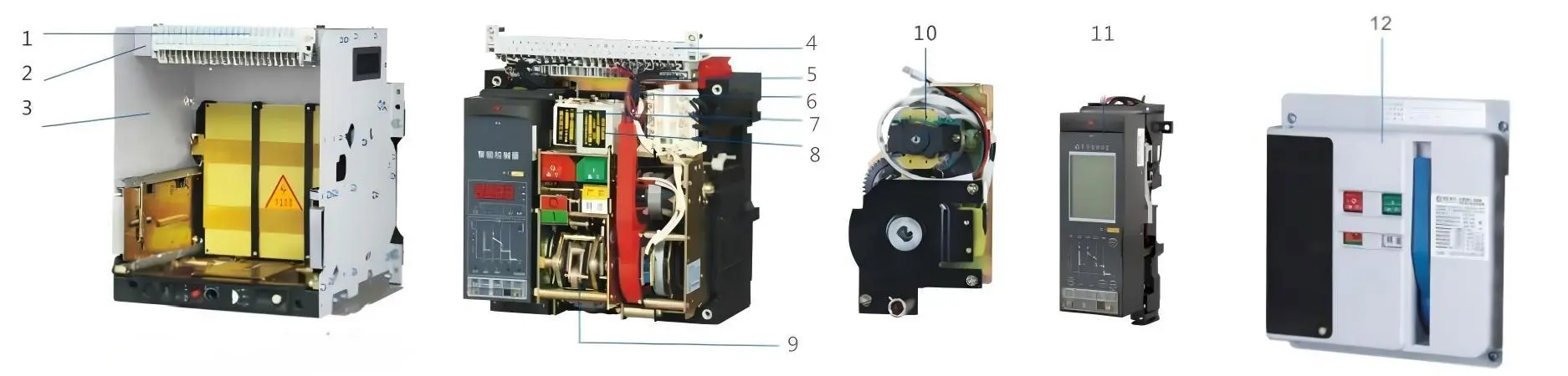
1.Secondary Circuit Terminal (Fixed)
2. Drawer Chassis
3. Safety Barrier
4. Secondary Circuit Terminal (Movable)
5. Auxiliary Contact
6. Shunt Release
7. Under voltage Release
8. Closing Electromagnet
9. Operating Mechanism
10. Motorized Smart Mechanism
11. Intelligent Controller
12. Front Panel
Technical Parameters
| Category | 2000A Frame Level | 3200A Frame Level | 4000A Frame Level | 6300A Frame Level | |
| Rated Current (A) | 200,250,315,400,500,630,800,1000,1250,1600,2000 | 2000,2500,2900,3200 | 3200,3600,4000 | 4000,5000,6300 | |
| Total Number of Operating Cycles | 10000 | 5000 | 5000 | 2000 | |
| Rated Short-Circuit Breaking Capacity Icu (kA) O-Co | 400V | 80 | 100 | 100 | 120 |
| 690V | 50 | 65 | 65 | 80 | |
| Rated Short-Circuit Making Capacity nxlcu (kA) / cosA | 400V | 176/0.2 | 220/0.2 | 220/0.2 | 264/0.2 |
| 690V | 105/0.25 | 143/0.2 | 143/0.2 | 187/0.2 | |
| Service Short-Circuit Breaking Capacity Ics (kA) O-C0-Co | 400V | 50 | 65 | 80 | 100 |
| 690V | 40 | 50 | 65 | 80 | |
| Rated Short-Time Withstand Current Icw (kA) 1s, 0.4s, 0-Co | 400V | 50 | 65 | 65/80(MCR) | 85/100(MCR) |
| 690V | 40 | 50 | 50/65(MCR) | 65/75(MCR) | |
| Operating Voltage & Power Requirements | |||||
| Power Required Rated Operating Voltage | AC(50Hz) | DC | |||
| Unit | AC220V | AC380V | DC110V | DC220V | |
| Shunt Release | 24VA | 36VA | 24VA | 24VA | |
| Undervoltage Release | 24VA | 36VA | - | - | |
| Closing Electromagnet | 24VA | 36VA | 24VA | 24VA | |
| Motorized Operating Mechanism | 2000A | 85VA | 85VA | 85VA | 85VA |
| 3200A,4000A | 110VA | 110VA | 110VA | 110VA | |
| 6300A | 150VA | 150VA | 150VA | 150VA | |
| Intelligent Controller Power Supply Voltage | AC220V,AC380V,DC220V,DC110V | ||||
| Note: The reliable operating voltage range is 70%-110% for shunt release, and 80%-110% for closing electromagnet and operating mechanism. | |||||
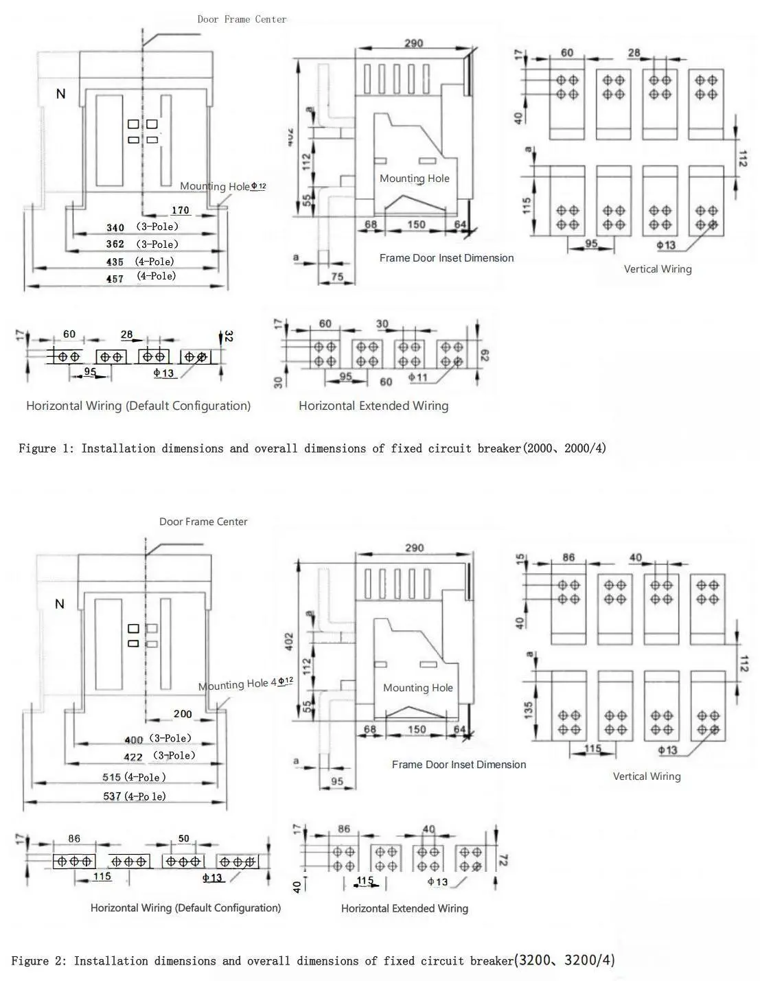
Installation dimensions and overall dimensions
| Installation dimensions and overall dimensions | In(A) | a(mm) | b(mm) | e(mm) |
| Fixed circut breaker (2000,2000/4) | 400-800 | 10 | 95 | 38 |
| 1000-1600 | 15 | 105 | 48 | |
| 2000 | 20 | 115 | 58 | |
| Fixed circut breaker (3200,3200/4) | 2000-2500 | 20 | 115 | 23 |
| 2900-3200 | 30 | 135 | 43 | |
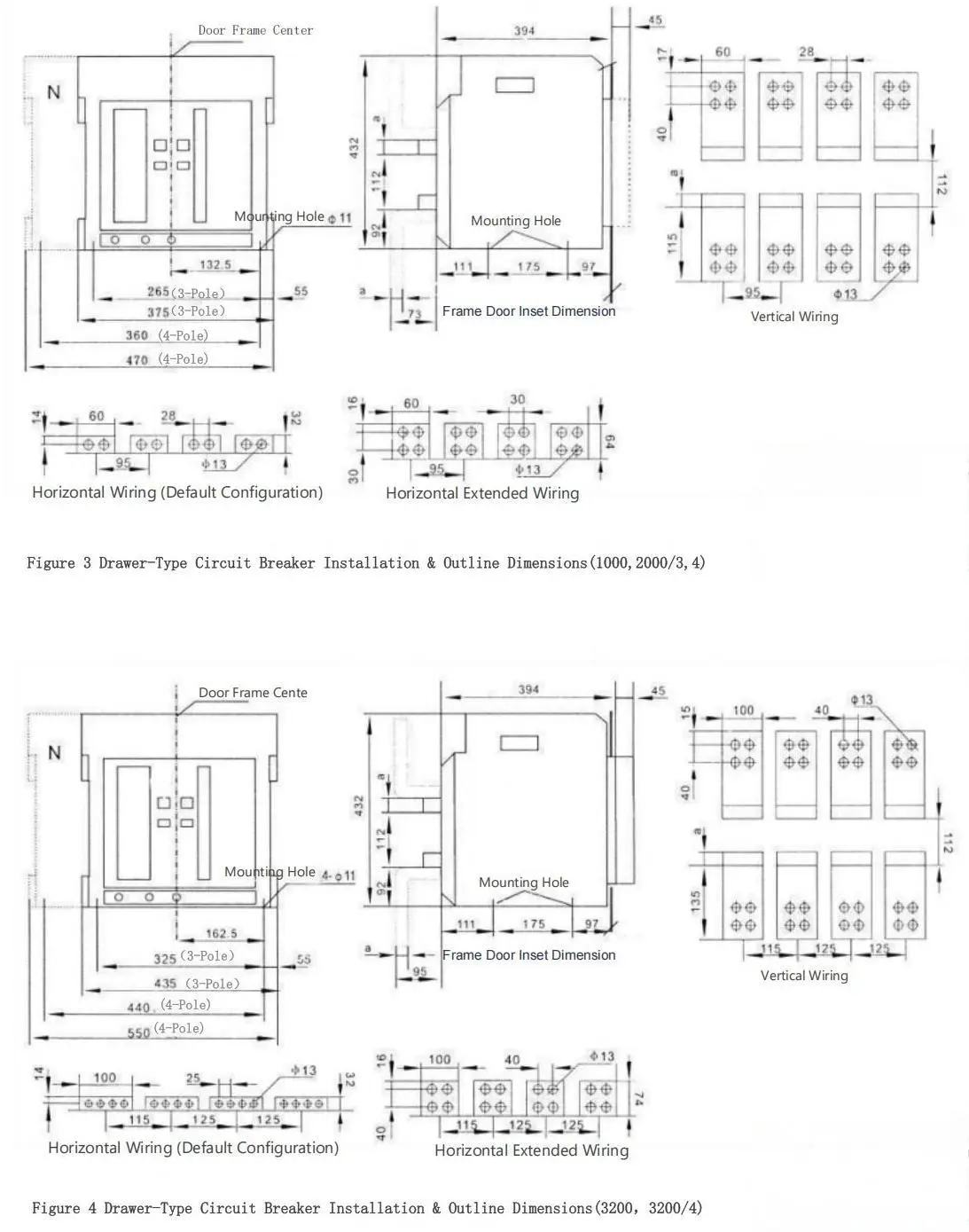
| Drawer-Type Circuit Breaker (1000,2000/3,4) | 400-800 | 10 | 95 | 3 |
| 1000-1600 | 15 | 105 | 13 | |
| 2000 | 20 | 115 | 23 | |
| Drawer-Type Circuit Breaker (3200,3200/4) | 2000-2500 | 20 | 115 | 58 |
| 2900-3200 | 30 | 135 | 78 | |
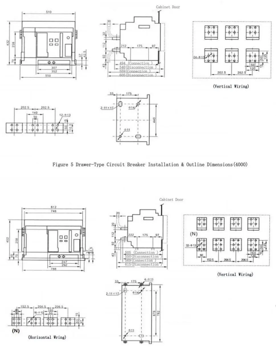
| Drawer-Type Circuit Breaker (4000) | Note: The horizontal center-to-center distance between the panel and circuit breaker shall be 57.5mm | |||
| Drawer-Type Circuit Breaker (4000/4) | Note: The horizontal center-to-center distance between the panel and circuit breaker shall be 206.5mm | |||
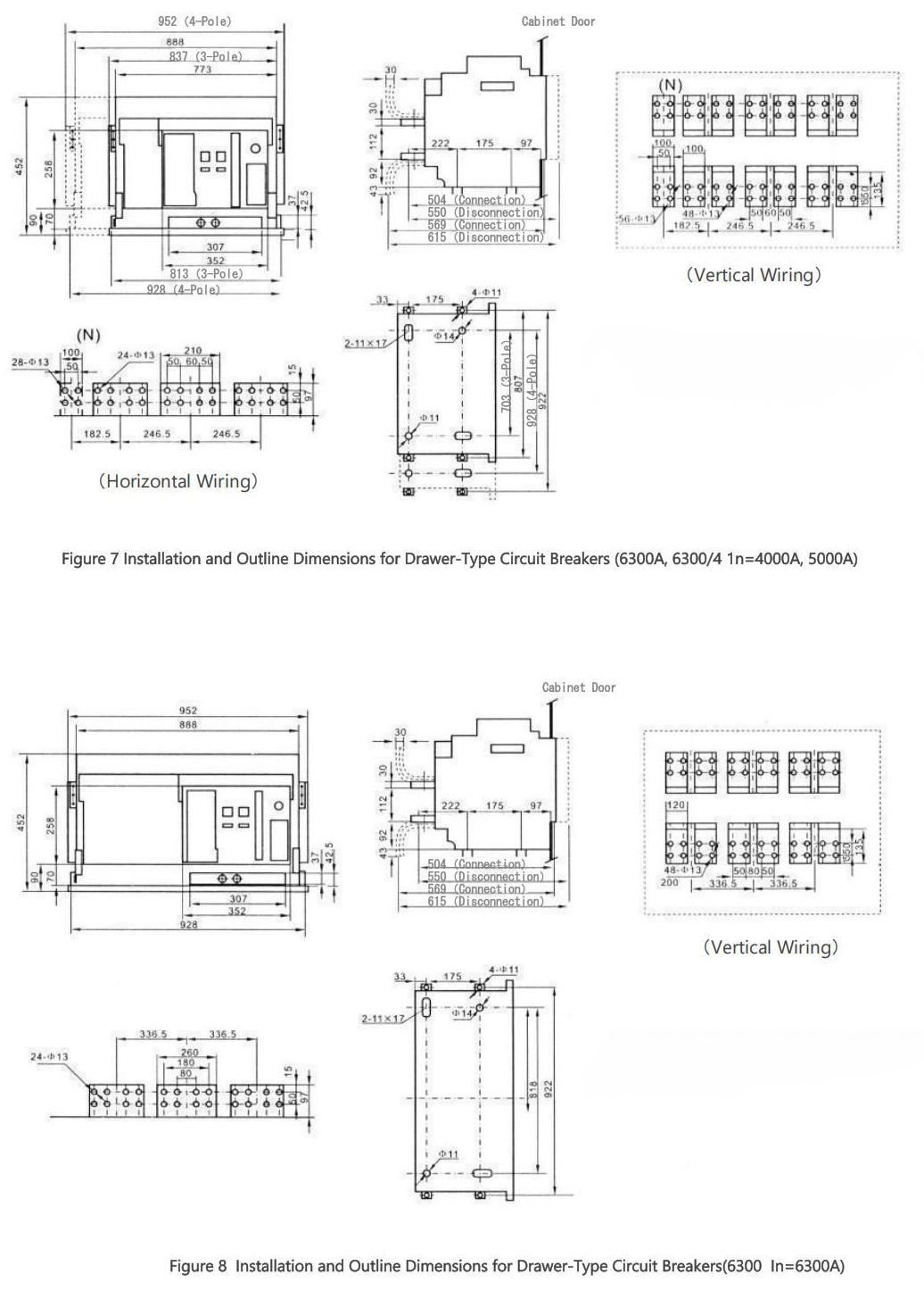
| Drawer-Type Circuit Breaker (6300A,6300/4 In=4000A,5000A) | Note: The horizontal center-to-center distance between the panel and circuit breaker shall be 189mm(3-pole), 246.5mm(4-pole) | |||
| Drawer-Type Circuit Breaker (6300 In=6300A) | Note: The horizontal center-to-center distance between the panel and circuit breaker shall be 246.5mm | |||
| Drawer-Type Circuit Breaker (6300A) | Note: The horizontal center-to-center distance between the panel and circuit breaker shall be 304mm | |||
◆ Fixed circuit breaker Installation & Outline Dimensions (Refer to Figures 1,2)
◆ Drawer-Type Circuit Breaker Installation & Outline Dimensions (Refer to Figures 3,4,5,6,7,8,9)

User connection busbar specifications and quantity (See the table below)
| Rated Current | External Copper Busbar Specification | Number of Bars per pole | Rated Current | External Copper Busbar Specification | Number of Bars per pole |
| 630A | 40×5 | 2 | 2900A | 100×10 | 3 |
| 800A | 50×5 | 2 | 3200A | 120×10 | 3 |
| 1000A | 60×5 | 2 | 3600A | 120×10 | 4 |
| 1250A | 80×5 | 2 | 4000A | 120×10 | 4 |
| 1600A | 100×5 | 2 | 5000A | 120×10 | 5 |
| 2000A | 100×5 | 3 | 6300A | 120×10 | 6 |
| 2500A | 100×5 | 4 | - | - | - |