


 Claire
 Mr.Fu
Mr.Fu

 Claire

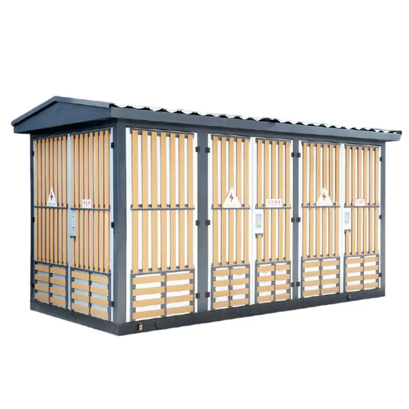
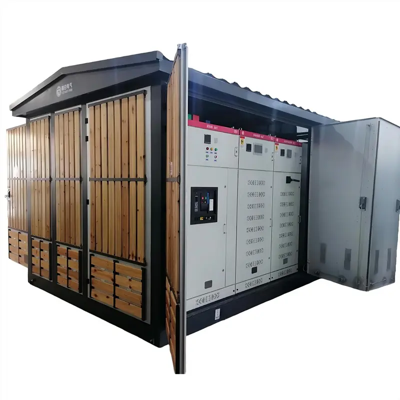
YB□-12 Prefabricated Transformer Substation for Power Distribution
Type Designation
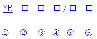
| 1 | Prefabricated Substation |
| 2 | Structural Feature: P-Triangular Layout; M- Rectangular Layout |
| 3 | Design Serial Number |
| 4 | Rated Voltage on High-Voltage Side (kV) |
| 5 | Rated Voltage on Low-Voltage Side (kV) |
| 6 | Rated Capacity of Transformer (kVA) |
Operating Conditions
Altitude: ≤ 1000m
Environmental temperature: -25 ℃~+40 ℃, (highest monthly average temperature+30 ℃, highest annual average temperature+20 ℃)
Relative humidity: daily average not exceeding 95%, monthly average not exceeding 90%
Seismic horizontal: horizontal acceleration of 0.4m/s2, vertical acceleration of 0.15m/s2
The installation location has no severe impact, no serious pollution or chemical corrosion, and no conductive dust explosion hazard in Egypt
Note: If ordering this product exceeds the above conditions, please consult with our company
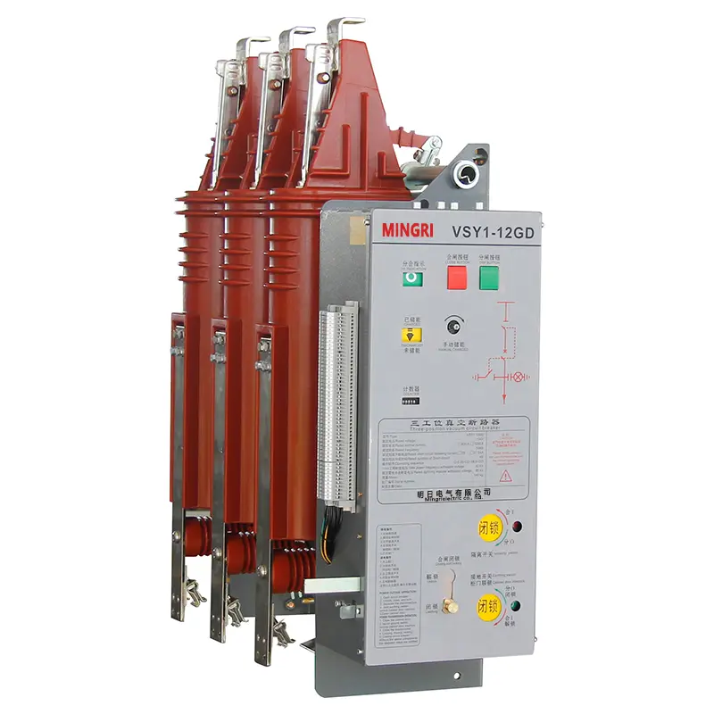
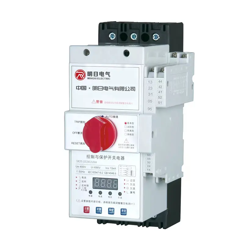
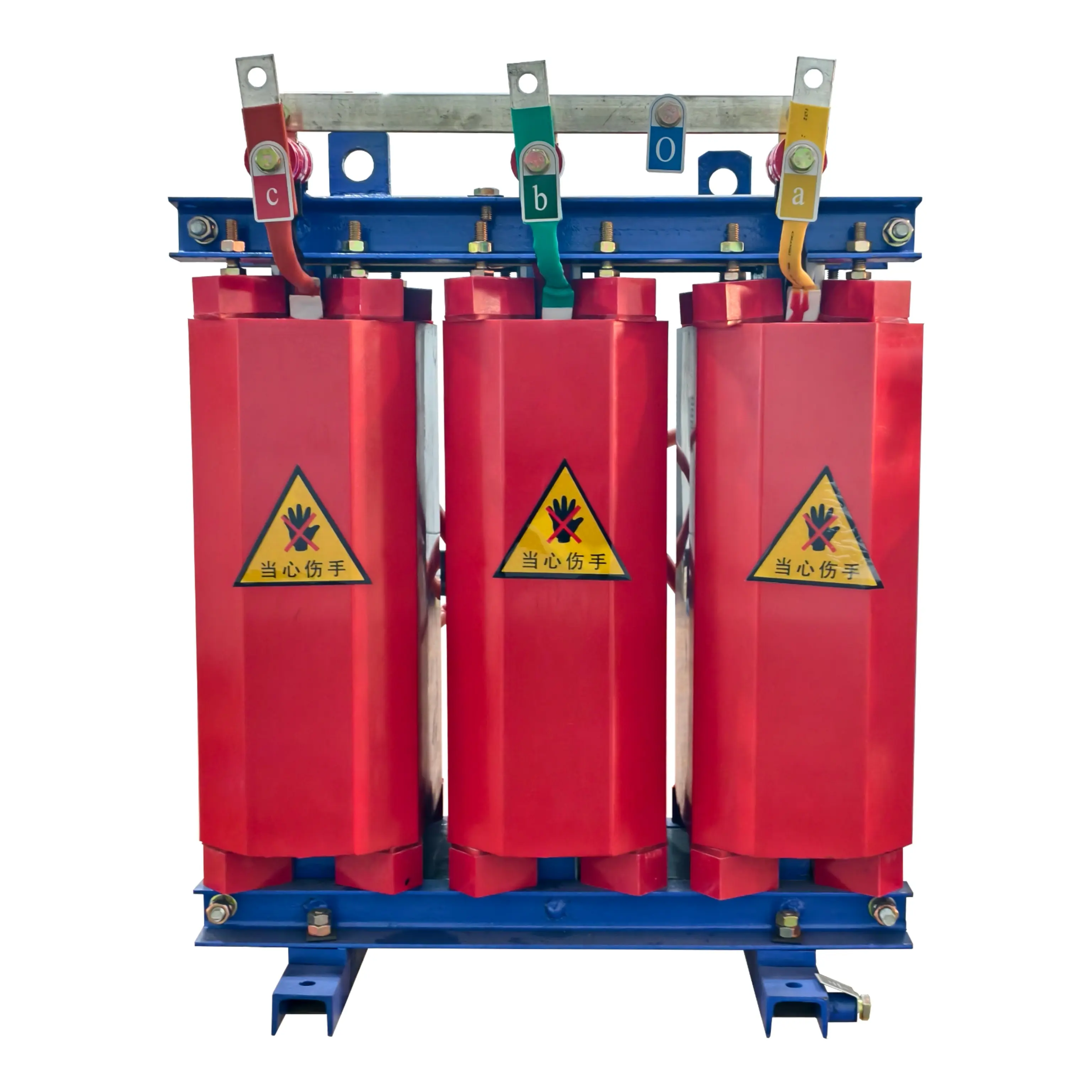
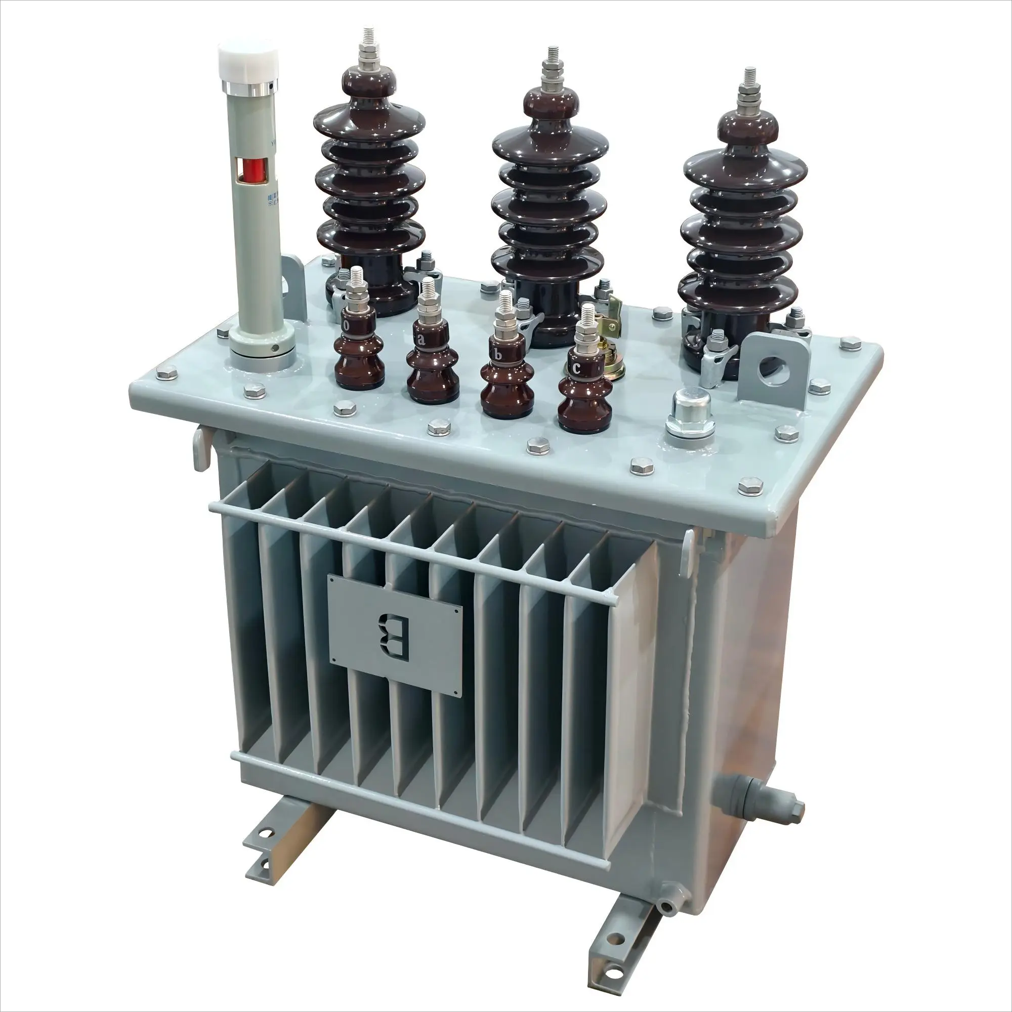
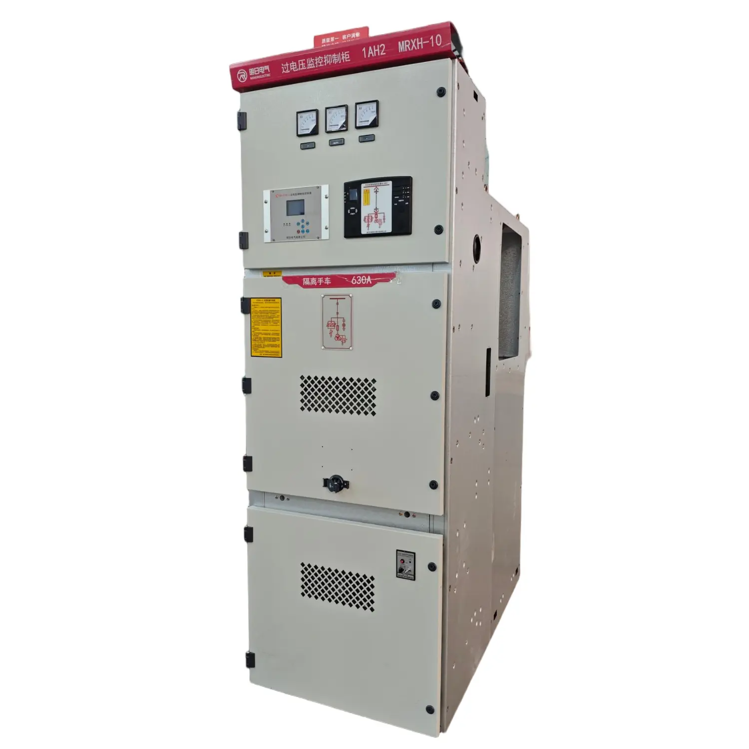
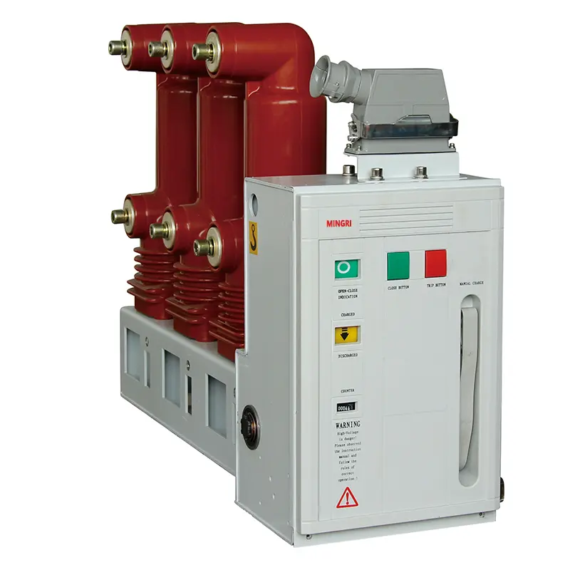
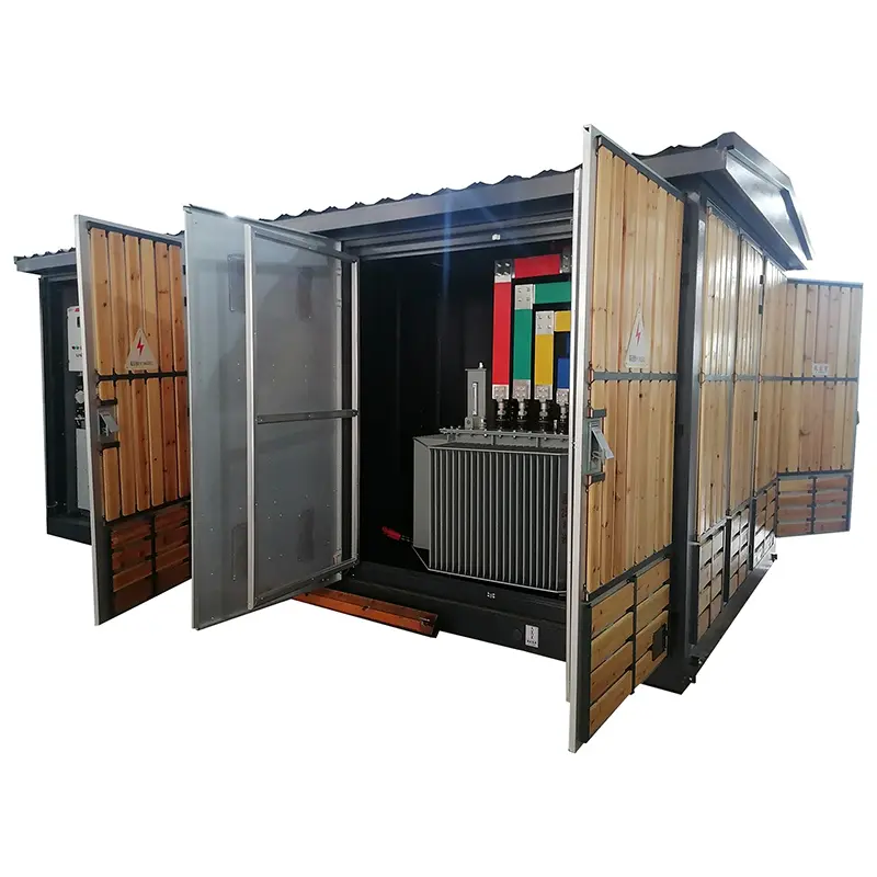
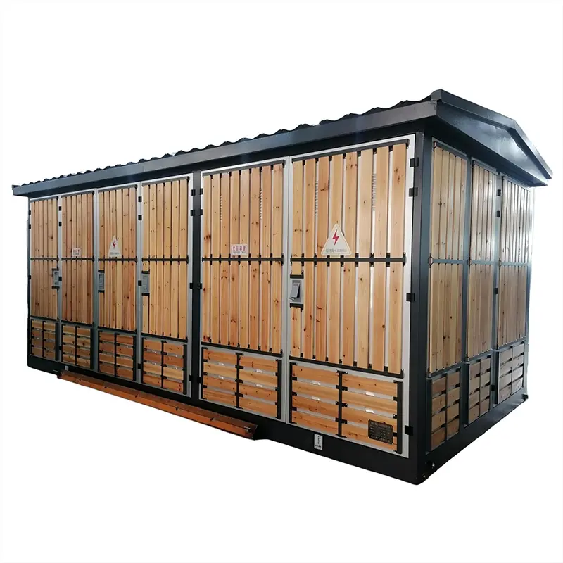
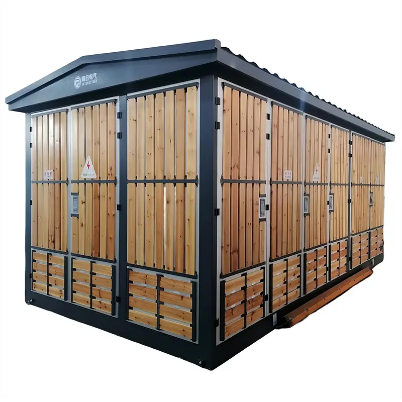
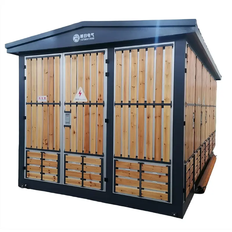
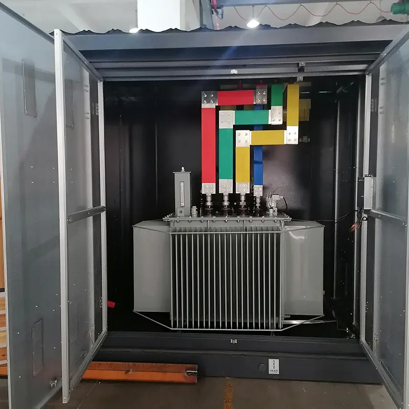
product Display
Technical Parameters
| No. | Name | Unit | High-Voltage Equipment | Transformer | Low-Voltage Equipment |
| 1 | Rated Voltage | kV | 6/10 | 60/0.4 10/0.4 | 0.4 |
| 2 | Rated Capacity | kVA | 50~1600 | ||
| 3 | Rated Current | A | 200,400,630 | 100~3200 | |
| 4 | Rated Short-Circuit Breaking Current | A | Load switch: 400-600 | 15~63kA | |
| kA | Composite switch: Depends on fuse | ||||
| 5 | Rated Short-Time Withstand Current | kA | 16,20(4S) | 15(1s) | |
| 30(1s) | |||||
| 6 | Rated Peak Withstand Current | kA | 31.5,50 | 30 | |
| 63 | |||||
| 7 | Power-Frequency Withstand Voltage (1min) | kV | Relative-to-ground &phase-to-phase:32/42 | 25/35 (oil immersed) | ≤0.3,2 |
| Isolation gap:36/48 | 20/28 (dry type) | >0.3,2.5 | |||
| 8 | Lightning Impulse Withstand Voltage (Peak)0.88 | kV | Relative-to-ground &phase-to-phase:60/75 | 60/75 | |
| Isolation gap:70/85 | |||||
| 9 | Enclosure Protection Level | ||||
| 10 | Noise Level | ab | IP23 | ||
| 11 | Applicable Standards | GT/T 17467 "Prefabricated High/Low-Voltage Substations" | 55 | ||
| DL/T 537 "Technical Conditions for Ordering 6-35kV Box type Substations" | |||||
| Note:For transformers with a capacity below 200kVA,items 5&6 are not required. | |||||
Installation Dimensions Diagram
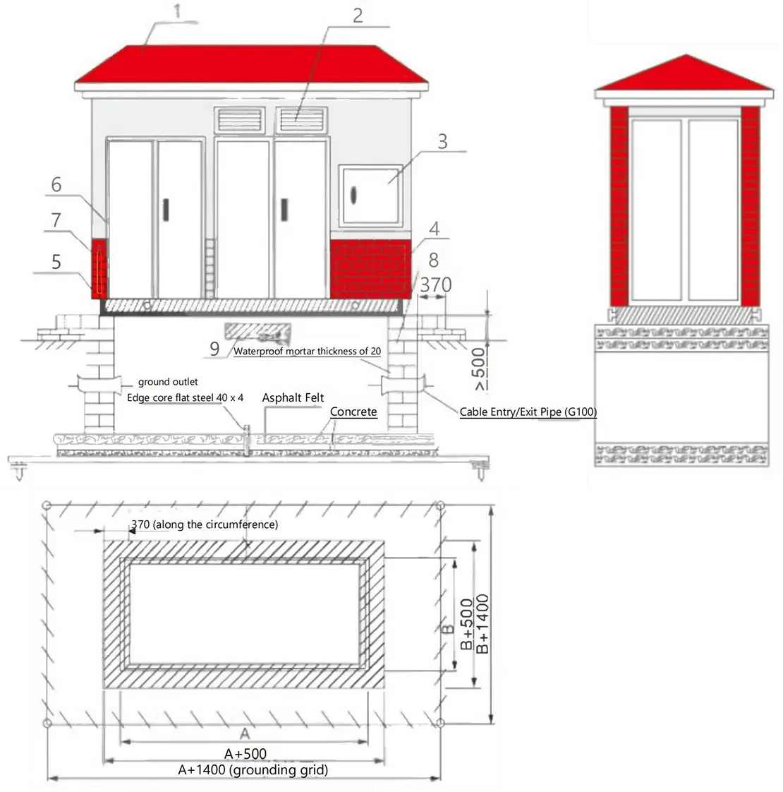
1. Roof
2. Louvered Vent
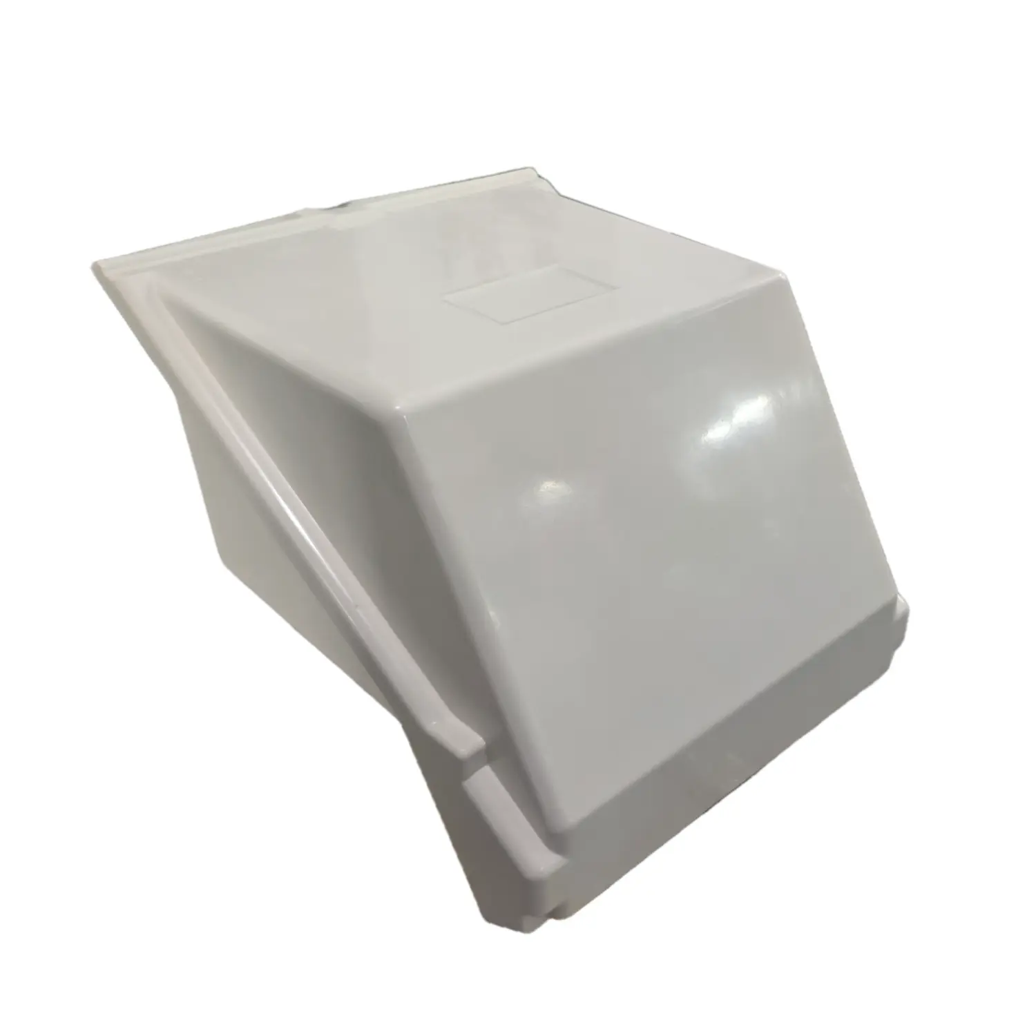
3. External Metering Box
4. Lifting Ring
5. Channel Steel Base Frame
6. Door
7. Strip Brick/ Brick-Pattern Cladding
8. Concrete Foundation
9. Foundation Ventilation Opening
Note: A and B are the external dimensions of the substation base
Ordering Notice
Product operating site and special requirements:
1. Provide product ordering drawings, which should include wiring diagrams and indicate transformer capacity, main component model specifications, distribution branch circuits, and capacity
2. When it is necessary to configure electric energy metering and reactive power automatic compensation devices, the requirements for the configuration of the metering meter and transformer should be provided, and the capacity of the compensation capacitor should be indicated
3. Specify the requirements for surface treatment of the product